Squirrel Detector Project
I looked out my window the other day and saw a squirrel munching on the wires of my solar powered LED string. It managed to snip off a two foot section of wire before disappearing below my deck, dragging the wire with it. I ran out the door to stop it but it was gone by then. I knew where it went.
The deck on my house is high up, a full story over the walk out basement. Below the deck is a shed formed by plywood sheets attached to the deck support posts with a roof made of corrugated fiberglass sheets. See the photo below:
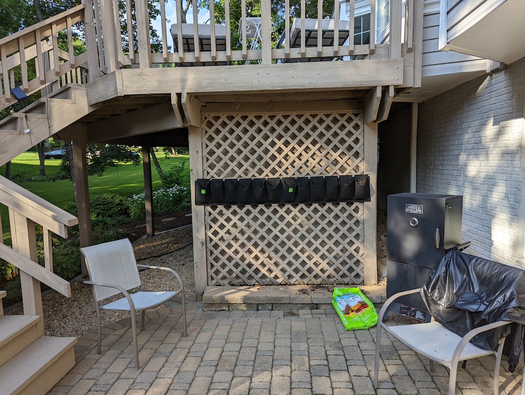
The lattice wood is purely decorative. At the top of the lattice is a piece of wood trim that hides the open space between the roof of the shed and the decking above. There is about ten inches of vertical space between the shed roof and the deck. It makes a nice area for a squirrel to build a nest. And that is exactly what she has done. If she hadn’t been so greedy to purloin my LED wires I might not have noticed the nest.
Now I generally like critters and I tolerate squirrels transiting the deck gathering maple seeds. But nesting in the woodwork is too much for me to tolerate. I can see the signs, now that I am looking, of damage to the wood from their compulsive gnawing. There are plenty of trees to choose from. So I got rid of the nest.
Yet the creature keeps coming back to rebuild. I need to make this space unpleasant. There are many things to try involving chemistry, carpentry, and etc. But I wanted to create an electronic solution.
How about a motion detector driving a buzzer?
This is the battle ground:
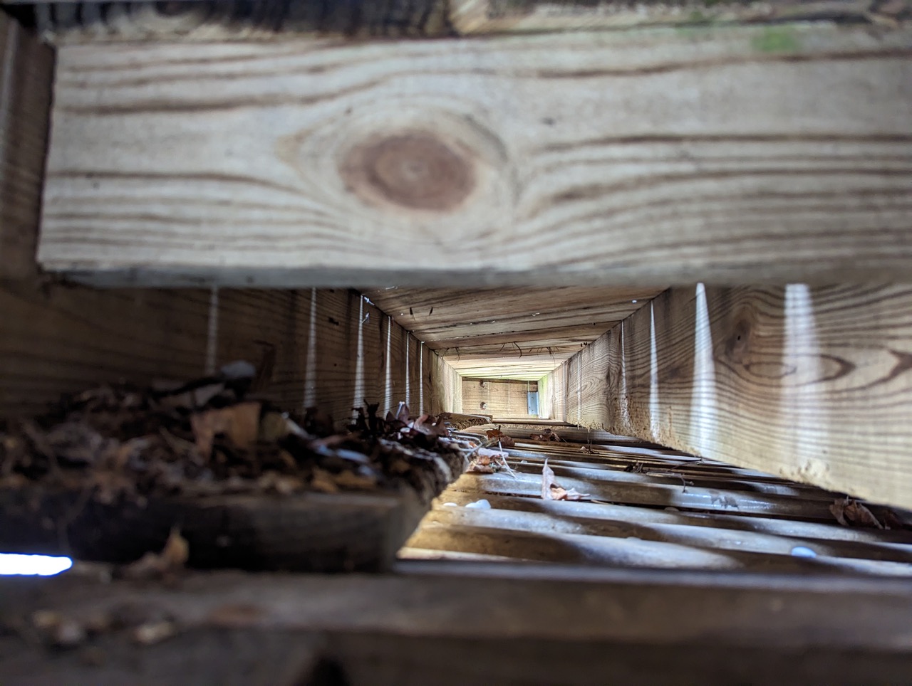
Before I removed the nest this area was packed with azalea branches and maple leaves. I couldn’t get it all out because I can’t get in there. I took this picture by holding my phone up into the space. Using a combination of tools and a garden hose, most of it is gone. The roof of the garden shed makes a nice floor to build a nest. There is about 3-4 inches between the shed roof and the beam on the right side of the picture, so the creature has a lot of options for ingress and egress.
Let’s assume that there are obnoxious sounds that will convince a squirrel that this is not the best place to raise a family. If it sounds off whenever the creature is in this space she might leave it alone and head for the trees. Like any other technique regarding squirrel abatement, you don’t know if it will be effective until you try.
A Minimal Solution
Overview
This solution is the bare minimum of complexity and cost. It makes use of mostly available parts and repurposed items.
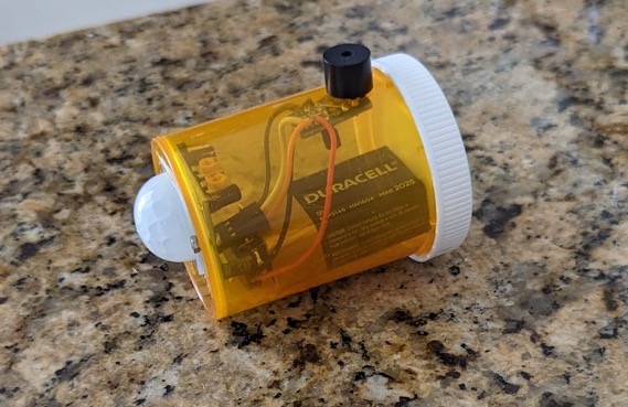
The solution consists of a PIR sensor, a 9 volt battery, and an active piezzo electric buzzer contained in a modified plastic medicine bottle. Yes, a medicine bottle.
Requirements
The following user stories capture the general requirements of the system.
As a user, I want the system to:
- detect the movement of a warm blooded animal within the confined space between the deck and the shed roof.
- detect repetitively. That is, as long as the critter is there it should be re-detected.
- emit a loud high pitched noise whenever motion is detected.
As a designer, I want the system to:
- be as small as possible
- be battery powered.
- be self contained with no exposed wires for the critter to chew.
- allow replacement of the battery.
- allow replacement of the buzzer if it wears out.
- allow adjustment of the circuit board for sensitivity and delay parameters.
As a squirrel, I want to:
- get the hell out of here (hopefully)
Phenomenology
Here is some background information about what is being sensed and how the device responds.
Schematic
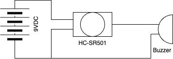
Below is an informal schematic of the electronics. The detector drives an active piezo electric buzzer directly using the 3.3V output of a Passive Infra-Red (PIR) sensor (off the shelf HC-SR501 clone). The buzzer draws 30mA and the PIR can supply a max of 60 mA so this should work. The specs for the buzzer show that at 3.3V the sound output is about 2 db less than at 5V. The curve flattens above 4V reaching a max of 90db at 5V. The spec does not include 9V but piezo buzzers typically can be driven at higher voltages without a problem. The question is whether the circuitry inside the buzzer can handle 9V. The circuitry within this buzzer is a mystery to me. I tested it with 9V to see if it can handle it and it seems to. No smoke came out and it buzzes.
The simple version uses the 3.3V output of the HC-SR501 to drive the buzzer.
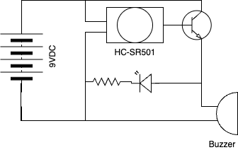
This alternative version uses a 2N2222 transistor to switch 9V into the buzzer. This voltage should be acceptable for this buzzer. An LED was added for breadboard tests but was not included in the deployed version.
Is a mechanical on/off switch needed? Once the battery is connected the device will start to make a loud noise as it detects me, so installation and battery changes will be loud. An alternative to a switch could simply be an IR opaque cover for the device to be removed when the device is deployed. I think I’ll go with that.
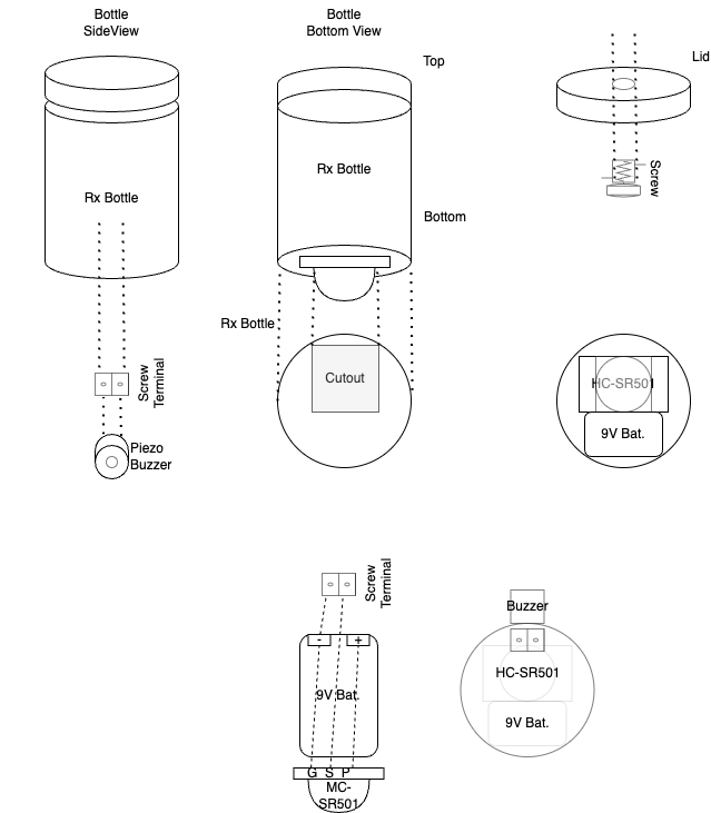
Packaging
More challenging than the electronics is the packaging. The HC-SR501 PIR sensor board is not waterproof yet it needs to have the dome of the sensor exposed to the area being monitored. The buzzer also needs to be exposed so that its noise volume is effective. Yet the package needs to be somewhat water resistant and no wires should be exposed, since this critter is known to chew on wires.
I looked around in my junk drawers for a suitable container. I have seen project boxes for sale for $10 or so. There are also 3D printed solutions but i don’t have a 3D printer. I wanted to reuse something I would normally throw away. I have a bunch of medicine bottles that I use for storing small parts. I found a short and fat bottle that would be barely large enough for the hardware.
In this design, the lid of the bottle is screwed into the wood of the enclosed space. The body of the bottle snaps into the lid. The device hangs from the wood. So how does the sensor fit into the bottle yet expose the sensor dome to the space?
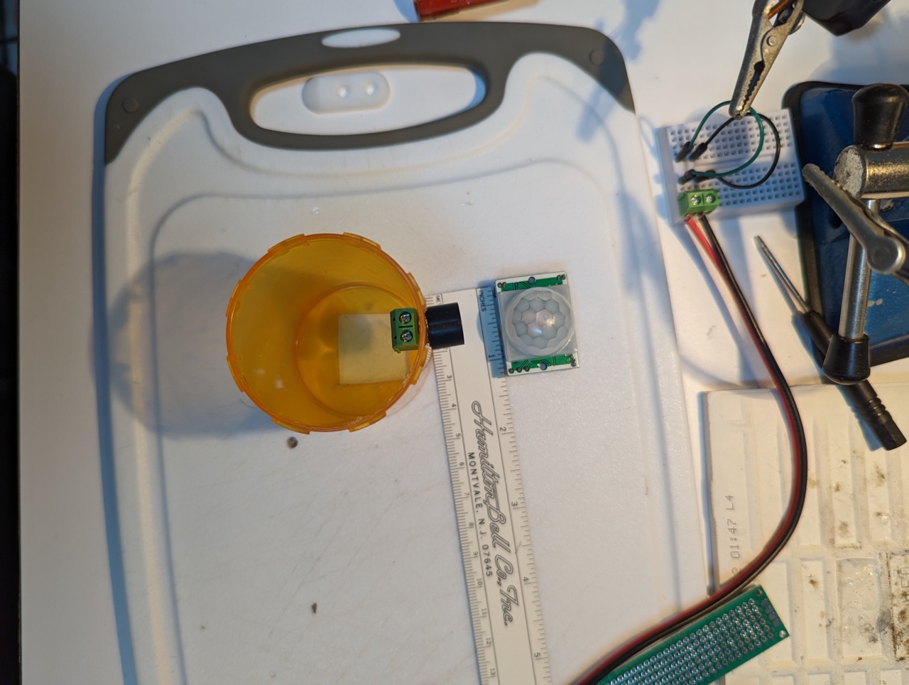
The HC-SR501 PIR sensor is a small board with the PIR sensor enclosed in a translucent plastic dome. The base of the dome connects to the board with a 23 mm square section that rises above the board slightly. By making a 23mm square cutout in the bottom of the bottle, the board sits upside down in the bottle with the dome protruding from the base of the bottle. The cutout is offset slightly so that a 9V battery sits in the bottle alongside the PIR board.
Rx Bottle Dimensions:
| Dimension | Meas.(mm) | Note |
|---|---|---|
| O.Diam | 49.11 | top |
| 48.48 | bottom | |
| In.Diam | 46.42 | |
| Depth | 64.07 |
PIR Board Dimensions:
| Dimension | Meas.(mm) | Note |
|---|---|---|
| Board W | 24.44 | top |
| Board L | 32.66 | |
| Dome | 23.13 | square |
Note that these requirements need to be addressed::
- allow replacement of the buzzer if it wears out.
- allow adjustment of the board potentiometers.
Both of these can be achieved by drilling holes in the side of the bottle. The buzzer, outside the bottle, passes its leads through two 1/16 inch holes drilled into the bottle. In my first design, the buzzer leads are not soldered but are fastened to a screw terminal block inside the bottle. The tension of this connection fastens the two objects to the bottle. The screws of the terminal face the opening to support installation and removal of the buzzer. The terminal block pins attach to the sensor board ground (G) and signal (S) pins via jumper wires soldered to the terminal block pins.
The terminal block pins can either be attached directly to jumper wires, or to a small pieces of perfboard (and soldered) along with the jumper wires. See two schematic options. A perfboard would have room for the transistor and LED but is not needed for the simpler option.
Note the piezzo buzzer polarity: the long lead is positive and there is also a small “+” embossed on one side of the package top.
Two holes (1/8 inch) allow insertion of a screwdriver to adjust the potentiometers on the PIR board for sensitivity and delay time. This can be done anytime and is deferred for now.
Another Approach
I really wanted to use the terminal block on the inside of the bottle to anchor the buzzer on the outside. However, it turns out that the buzzer leads are too short to enter the terminal block fully. The thickness of the bottle wall takes some space away from the connection and the curvature a little more. It is only about 3mm but that is enough to make assembly difficult. Also, the terminal block uses a tapered anvil to press the wire onto the conductive plate. So if the thin wire moves to the side of the terminal opening, or if it is a little bit too short, then it won’t anchor properly. Given these issues, it’s time to try another approach.
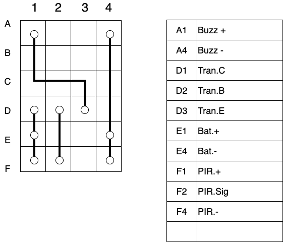
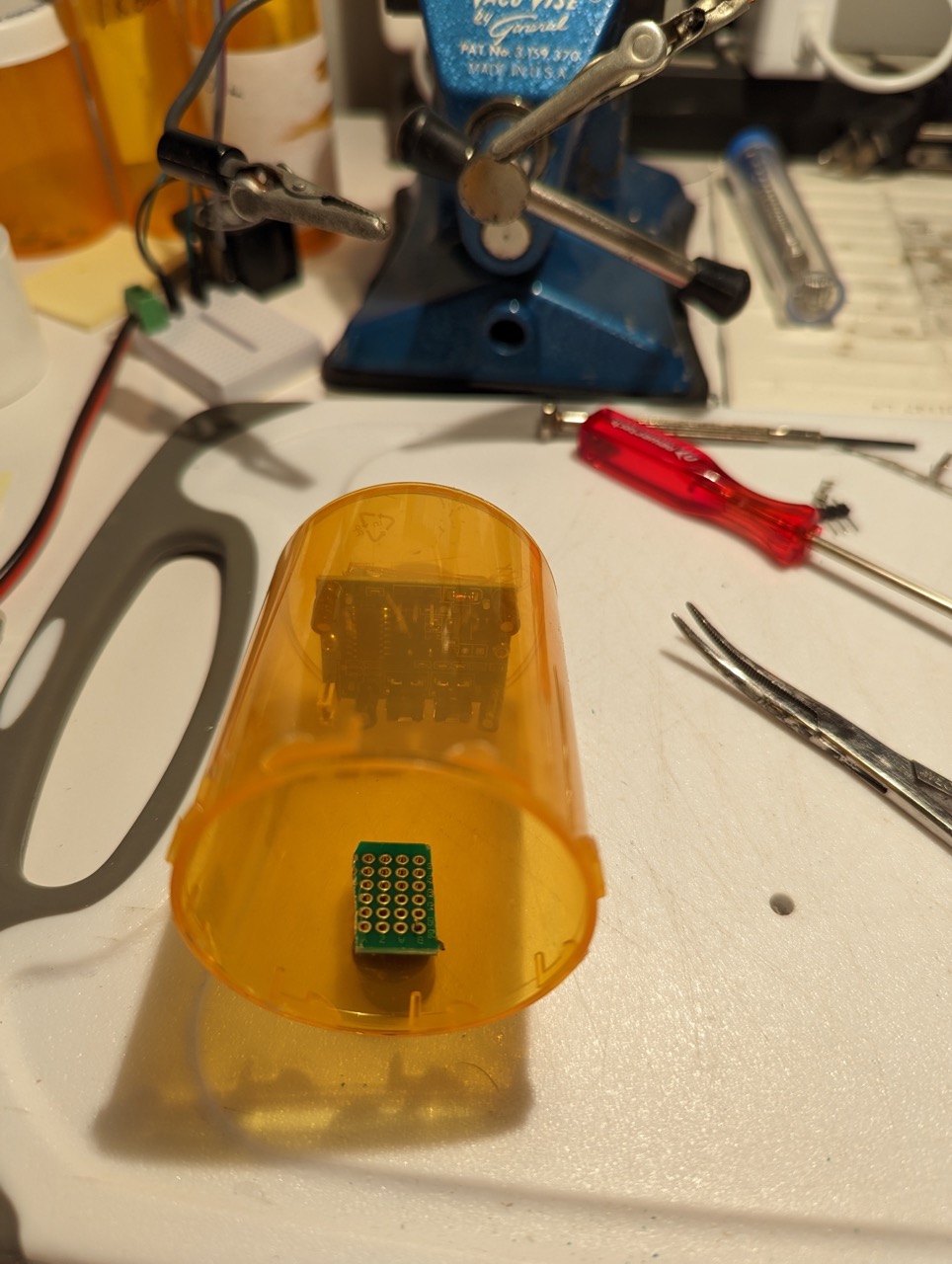
A 4 hole by 6 hole section of perfboard was cut with scissors to make the board below. Like the terminal solution above, the buzzer outside the bottle will be anchored by its pin connection to the perfboard in the bottle. But now the buzzer leads are soldered to the board at A1 and A4. The buzzer leads are barely long enough to go through the holes in the board but I think it will hold. The buzzer can still be replaced but it requires a soldering iron.
The other components are connected as shown below. This design mostly follows the alternate schematic which uses a 2N2222 transistor to drive the buzzer with 9V rather than the 3V of the HC-SR501. This should give about 2db more noise. The LED was not included as it is not needed.
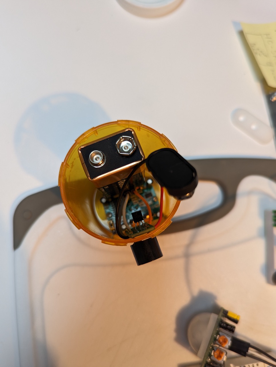
Top View
Gallery: The Assembly
Using a vintage Casco Electr-O-Tool Kit, I cut a 23 mm square from the bottom of the medicine jar.
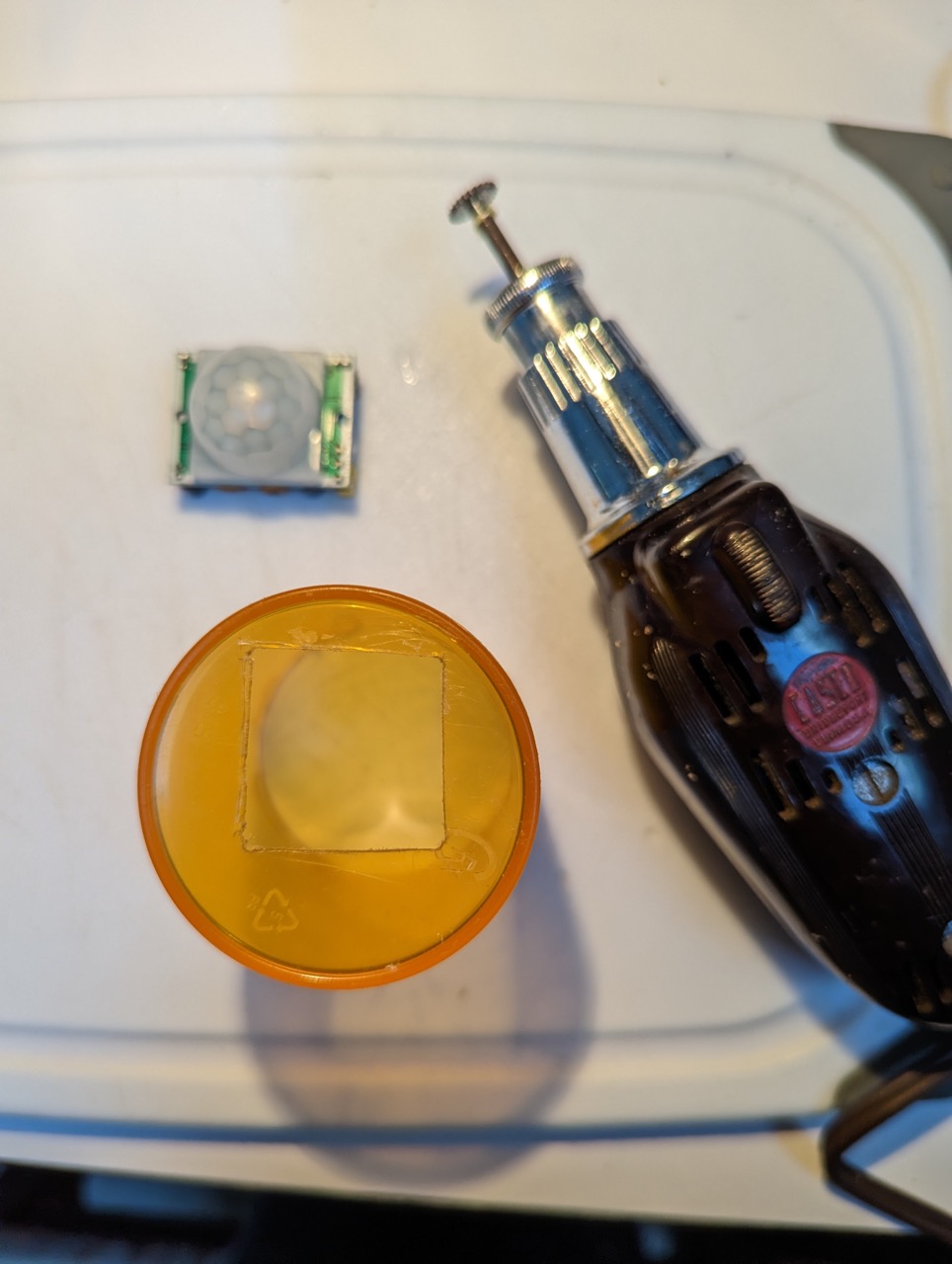
This gives just enough room to insert the dome of the PIR into the bottom of the jar. Flipping it over shows the business end of the detector. Two 1/16 inch holes are drilled into the jar bottom so that two M2 screws can fasten the the PIR to the jar.
Two additional 1/16 inch holes are drilled into the side of the jar for mounting the buzzer. As noted above, my first approach to fastening the buzzer didn’t work. It held long enough to take this picture. With different buzzers or terminal blocks it might work.
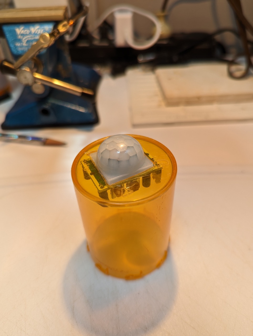
The second approach did work.
I soldered up the board outside the jar. With the board finished, except for the connection to the buzzer, the board was inserted into the jar and held with a hemostat while I pushed the buzzer leads through the holes in the jar and through the holes in the board. Once soldered into place, the board is now connected to the jar.
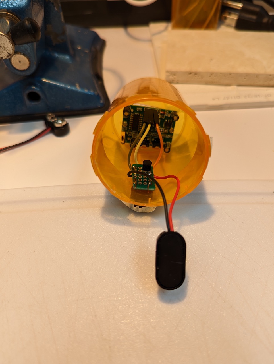
The buzzer wiggles a little but it is firmly in place.
Now the battery goes into the jar. It’s a snug fit but it works. I found that it fits better when the battery is upside down, it’s terminals facing the PIR.
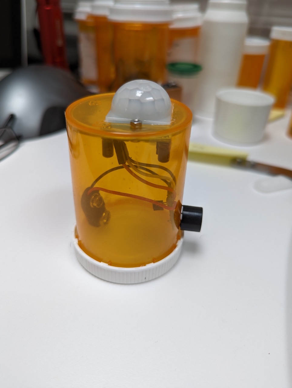
The finished product:
The deployment:
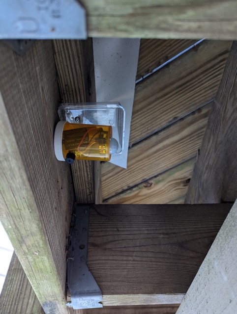
A rain shield was added above the bottle. It came from the packaging of my favorite parmesan crisps snack. I’l have to wait for the next storm to see if it is effective.