- Smoker Controller Hack
- 1 Scope of the Hack
- 2 Referenced Documents
- 3 Current System
- 4 Changes
- 5 Concepts for the Proposed System
- 6 Operational Scenarios
- 7 Summary of Impacts
- 8 Analysis of the Proposed System
- 9 Appendices
- SmokerController ConOps
Smoker Controller Hack
Concept of Operation
After The Hack
Preface and TL;DR
This is about rescuing a seemingly serviceable electric smoker from the trash heap. The primary known-unknown is that the console display panel is flakey but I don’t know why. This leads to a general assumption that replacing the top control module would result in a workable smoker. It’s always the unknown-unknowns that get you. I have a lot of those given that I am not a hardware guy. I did take an elctronics course 40 years ago. But hardware is my new hobby and I like to read and learn so off I go. Join me in my adventure.
This document is written loosely following the IEEE Concepts of Operation format (IEEE Std 1362a-1998). In my work as a Systems Engineer the first thing anyone would ask when going on to a new project was,”Where the !#$% is the Conops?” So here it is.
The usual purpose of a conops document is to sell the decision makers in a organization that you are about to change something that will piss-off a lot of stakeholders in order to please others. Obviously that doesn’t apply to a hack like this but the format makes a good way to document what this hack entails.
Document Structure
- Scope
- Referenced Documents
- Current System Description
- Changes to the System
- Concepts for the Proposed Changes
- Operational Scenarios
- Summary of Impacts
- Analysis of the Proposed System
- Appendices
- A. Glossary
- B. Board Prototype
- C. Board Design
- D. Board Assembly
- Scope
1 Scope of the Hack
Identification
The system to be hacked is the control unit of a Masterbuilt electric smoker.
- Model: 20070512
- Serial Number: AB131336
- Date of Manufacture: Unknown
- Manufacturer: Masterbuilt
- Mfr Address: 1 Masterbuilt Court, Columbus , GA 31907
- Mfr Phone: 1-800-489-1581
- Country of Manufacture: China
- Voltage: 120V AC 60Hz
- Current: 10A
- Power: 1200W
- Dimensions (inches): 40 (h) x 22 (w) x 16 (d)
Description of the system:
The smoker is a vertical 40 inch insulated box with a glass door opening to a four shelf cooking area (although this one only has two shelves). Below the lowest shelf is a 1200 Watt electric heating element and a smoke box resting above the heating element. Wood chips are placed in the smoke box to produce smoke. The heating element and its controller has dual purposes that may conflict at lower temperatures:
- heating the wood chips to the smoking point of wood
- heating the cooking compartment to a temperature for slow cooking
I think this is typical of any smoker powered by something other than wood. I have another smoker powered by propane and it is a challenge to get smoke at the 180F I want for smoking salmon. But meats call for a higher temperature, like 225F so that is less of a problem. I have never used a functioning Masterbuilt electric smoker so this will be interesting.
The electrical components of the system are:
- resistance heating element
- controller board and display at the top front of the smoker
- power supply and high voltage relays in the bottom of the smoker supplying:
- 120 VAC power to the heating element via a relay
- Regulated 5 VDC power to the controller unit
- temperature sensor for controlling the oven box temperature
- temperature sensor providing information on meat temperature
- temperature sensor and current interruptor to safely shut the down the system when the oven box exceeds some limiting temperature
Purpose and Scope of this Project
The major components of the system appear to be working with the exception of the display unit of the controller board. The display unit, a four-digit seven-segment LED, is not easily replaceable. The cause of the display failure is unknown and may be due to other board failures.
When the unit is powered up the buttons can be used to blindly set a temperature and at that point the heating element goes on. It looks like the power supply and the heating element do not need to be replaced.
This project will replace the controller unit with a new display and controller. The other components will be left intact. The controller will be based on an Arduino Nano Every, because I have one to spare.
Pictures of the Current System
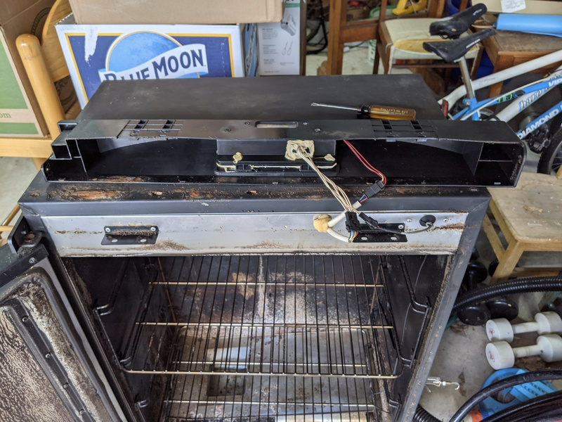
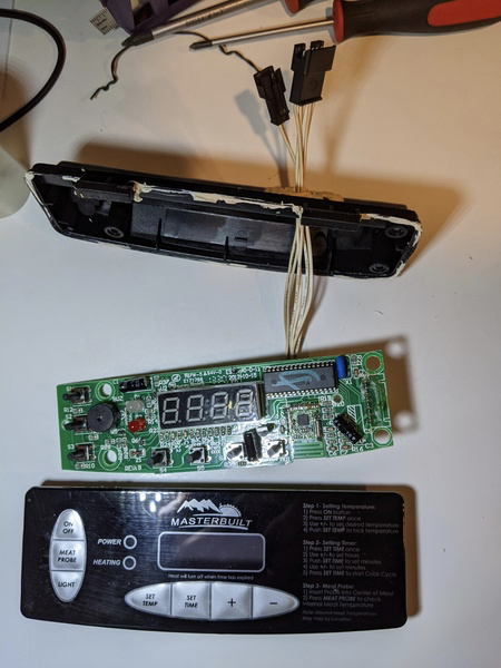
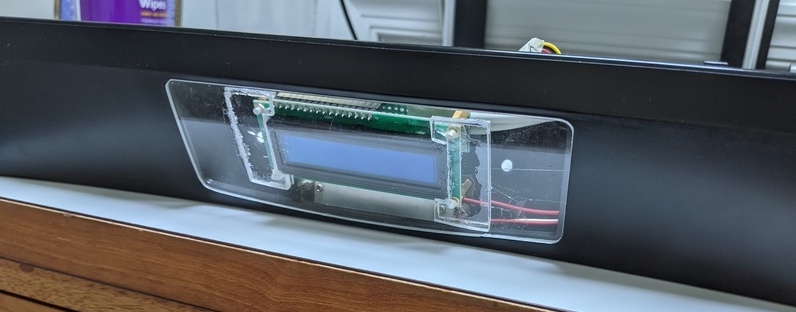
There are many Masterbuilt models with different features. This one has a curved console piece containing the controller module that hangs off the front of the smoker box above the door.
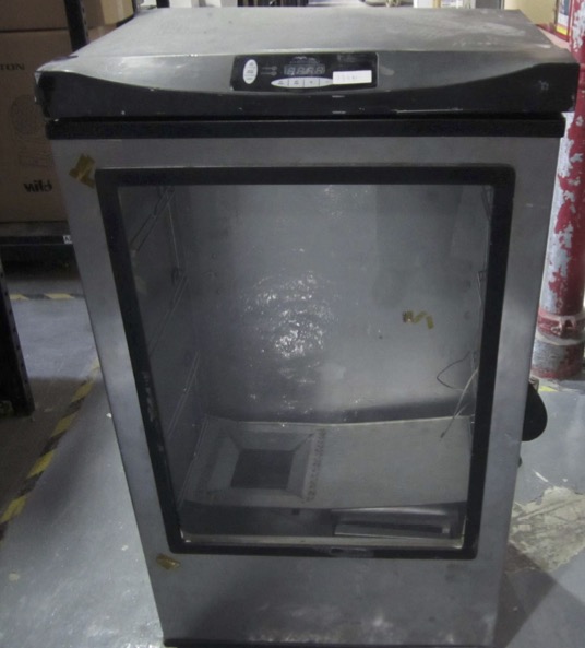
Before the Hack
The control panel has a single 4-digit 7-segment LED and seven buttons. The burrons are used to display different parameters on the 4-digit display.
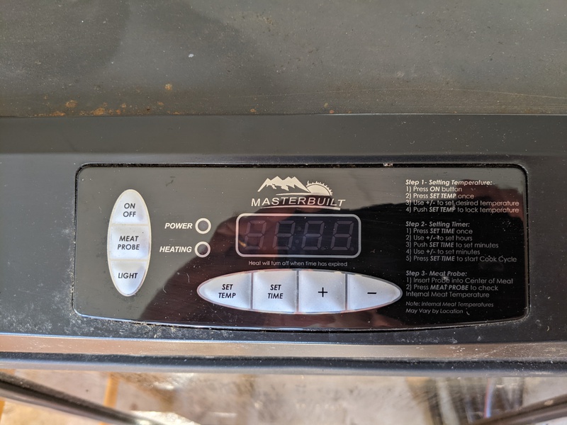
OEM Control Panel
Hardware Parts Needed
- Arduino Nano Every
- OLED display unit, New Haven Display model NHD-0216-KZW-AG5
- Plexiglass sheet, 1/8 inch thick
- Circuit board (perf-board)
- wire and connectors
- resistors and capacitors
- stand-offs, shrink tubing, and etc.
- Referenced Documents
2 Referenced Documents
This project began with the conviction that I could probably replace the Masterbuilt Model 20070512 smoker’s controller module with an Arduino based controller. This despite the fact that I didn’t know a lot. I’m a software developer so I knew that code would not be a problem. I had taken an electronics course 40 years ago where I learned enough to be dangerous. If only I could remember it. Then there is the smoker. Abandoned by the manufacturer, I was on my own to discover its secrets.
Fortunately there is the internet.
Manufacturer’s Web Site
The Masterbuilt site has information about its current products which was useful for background information. They sell parts for my smoker, but not the controller (anymore). The site is useful for determining which parts are compatible with my model. So I did spend some time there.
User Manual
I could not find the user manual for Model 20070512 on the Masterbuilt site but another site Appliance Factory Parts did have it. Also the FCC site decribed below had the manual.
OEM Engineering Drawings
The manufacturer has made several filings with the US FCC which shed light on the design of the system. It is difficult to correlate these filings with the Model 20070512 but inferences can be made.
The label attached to the back of the unit gives the FCC ID as ESQ-3040C4 as shown below. However, the FCC Filing for Masterbuilt Manufacturing, Inc. ESQ-3040C4 has a circuit diagram that shows a SSCU2L4 micro controller. The circuit board for my smoker does not have an SSCU2L4. It has a TMP86FH09 chip.
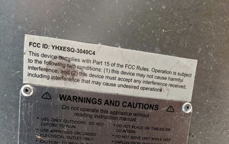
FCC ID
Now it turns out that the FCC filing for ESQ-3040C3 has a circuit diagram that shows a TMP86FH09 micro controller. This is the controller in my model. It is hard to see in this photo but it definitely is a TMP86FH09.
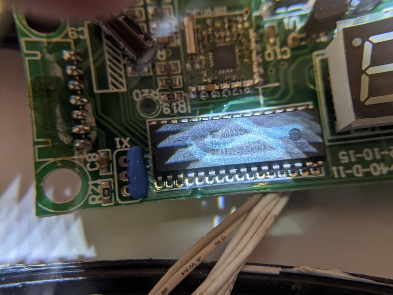
Soul of the Old Machine
Several files of photos, drawings, and a user manual support this. All of the other filings use a different MCU. While this is not definitive it is the best guess I have. However, this filing does not document the power supply board.
As luck would have it, the filing for ESQ-3040C2 does have a schematic for the power board. While this filing does not have the same MCU this power board schematic appears to have the same pin connectors as my control board. My testing of voltage and resistance support, but do not prove, that this is a substantially similar power board.
At this point I should mention that I am not an EE so take everything I say with a grain of salt. Also, the factory may have had running engineering changes. Your experience may vary.
OEM MCU Specifications
The OEM smoker controller board is built around an MCU for which documentation is available: TMP86FH09ANG
There is a lot of information here. Like an Arduino, it uses 10-bit ADC for its analog input pins. This reassured me that replacing the OEM board was feasible.
Display Module
The spec.sheet for the New Haven NHD-0216KZW-AG5 OLED module has all the information needed to hook one up.
I got additional tips from the New Haven Display Forum.
Smoker Forums
I got a surprising amount of information, not all of it usable for my hack, at Smoking Meat Forums. These people are passionate. There is a lot of talk about PID controllers and alternatives. My search method uses Google rather than local site searches. But Google searches keep coming back to this site. Good SEO there.
Electonics App
This iOS app, Electronics Engineer Helper, is like having an electronics textbook and an assistant to look up the short version of the answers for you. It has a voltage divider calculator which was helpful in biasing the thermistors into the Arduino’s ADC range.
Standards for Weatherproofing
When buying components it’s good to know how these things are rated for resistance to the elements. Wikipedia has a good article about Ingress Protection (IP) Rating. Come to think of it, Wikipedia has tons of information on many relevant topics. Days have been spent there. 3. Current System
3 Current System
Description and Deconstruction
Background
The smoker was acquired through a Craig’s List “free to anyone” posting. It is reported to work but the control panel is flakey. It is questionable that any of it works. This will have to be tested at some point before buying the project components. Some parts appear to be available via the manufacturer but others have fallen off the obsolescence cliff. The manufacturer website no longer has replacement controller units for this model. There are parts for later models that might be workable but perhaps not exact fits. Weather proofing in the current system is well thought out but may not work for the replacement components due to form factor changes.
Is it worth a call to the manufacturer to see if someone might suggest that part x will work in that model even though the website doesn’t list that model? No, of course not. Those days are long gone. Their 800 number refers you to their website.
I did create a support ticket but that resulted in a polite response that I am out of luck.
Before I took the unit apart, I cruised the internet for kindred spirits. There are a good number. Enough to encourage me. For example, a C64 collides with a smoker post on Hackaday.com . Available intelligence leads me to believe that the control unit’s inputs and outputs are low voltage DC wires linking to a relay which switches on and off the heating unit and an oven light. Additional wires power the control unit and feedback the temperature sensor readings. That means that the controller’s functionality is self contained and a simple replacement solution may be obtainable.
I have verified that only the controller head unit needs to be replaced. The power control module, located in the base of the smoker, contains a mechanical relay and the power supply for the head unit. The manufacturer website sells voltage control units for other models that are more complex than a simple relay. Need to test this if possible.
I have verified that the heating element works well enough to heat the oven to cooking temperature and hold it there. However the heating element may fail at some time and may need to be replaced. The manufacturer and others still provide replacement heating elements. This may be tested using an ohm meter; it should have around 20 ohms through the element contacts and no continuity between either contact and the casing. If any continuity exists to the casing the element must be replaced.
At this point I need to determine the relay input control voltage and protocol. I believe that it is a simple 5V to activate the heater and 0V to stop it but it could be the other way around. Also how does the controller get data from the box and meat thermo sensors? Do these function correctly?
Searching, I find:
- One source, for a different model, says there is a 4 wire connector: GND, 5VDC, heater on (presumably 5V digital), temperature sensor (presumably 0-5V analog).
- Same source suggested using a PID algorithm to control temperature in a way that avoids overshooting the targeted temperature. Ok, here is another rabbit hole to run down.
- Same source says temp sensor is a Negative Temperature Coefficient (NTC)) thermistor of 50K Ohms at room temp.
- Same source says the heat element is switched via a solid state relay unit (actually an electro-mechanicsl relay in my model) in the base of the smoker box and this unit is the power supply for the head unit.
More searching reveals an FCC filing for Masterbuilt ESQ-3040C3 having a circuit diagram that seems to fit my model. See the section Referenced Documents, OEM Engineering Drawings for my discussion of this source.
Now I need to deconstruct the device.
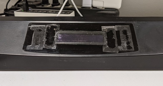
Description and Deconstruction
The control panel console is mounted at the top front of the smoking box at a slight angle. Its surface is curved heavily at the ends and slightly in the middle. The effect of this is to drain off rainwater as well as for visibility of the panel. The cross section of the control panel in the middle is almost triangular. At either end the cross section is rectangular.
OEM Control Panel
The console panel is removable with a few screws on the side and bottom of the panel. The control unit is encased in a plastic housing that is attached to the console panel by two screws with copious amounts of adhesive caulking to prevent water intrusion.
Console Removed
The control unit is connected to the smoker by three Dupont style plug connectors:
- 5-pin. Five white wires go from the controller into the smoker body.
- 2-pin. Two thermally insulated white wires go from the controller into the smoker body. My guess is that these two wires connect to the meat probe.
- 3-pin. Two red and one white wires go from the smoker’s lighting fixture into the smoker body, bypassing the controller. My guess is that these wires connect to the power board in the base of the unit and are relay controlled by the controller via data lines in the 5-pin wire bundle.
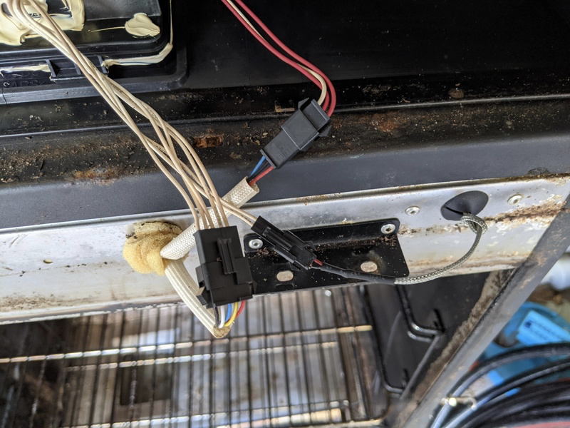
Controller to Smoker Connections
Wire Connectors
After some effort I was able to remove the sticky stuff from the control unit and open up the casing.
Control Unit
A closer look at the control board shows it to be quite densely populated with miniature components that I am not likely to duplicate with the resources at my disposal.
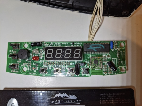
Control Board Front
The back of the board confirms this. Look at all those traces!
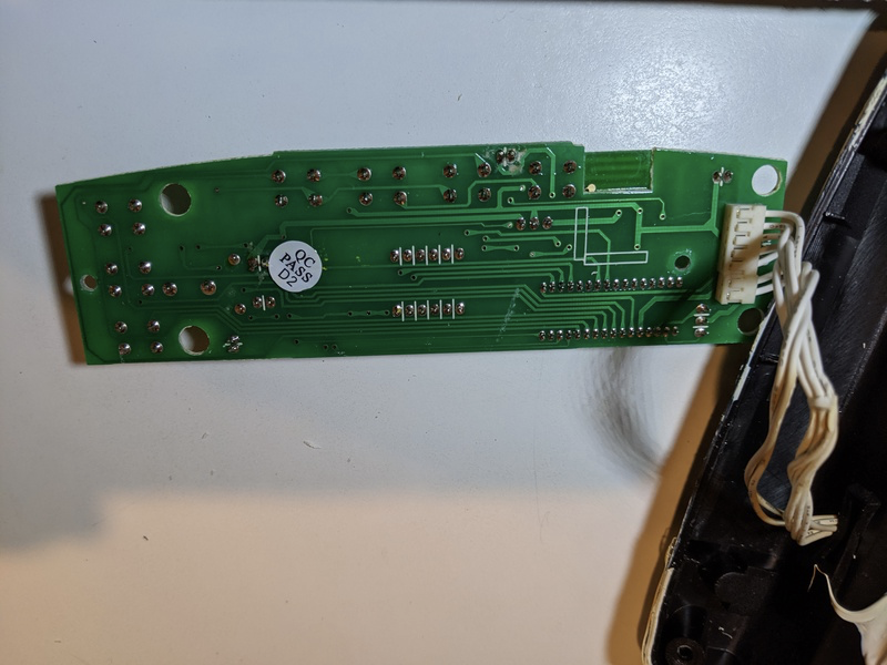
Control Board Back
The micro controller driving this unit is a Toshiba TMP86FH09.

Micro Controller Chip
The controller chip is adequately documented. Just search for TMP86FH09 and many datasheet sources pop up. Which of these are canonical? I don’t know. I take my chances and download one. This combined with the FCC schematics will, hopefully, inform me on how to build an equivalent Arduino based controller.
Divining the Wiring for Model 20070512
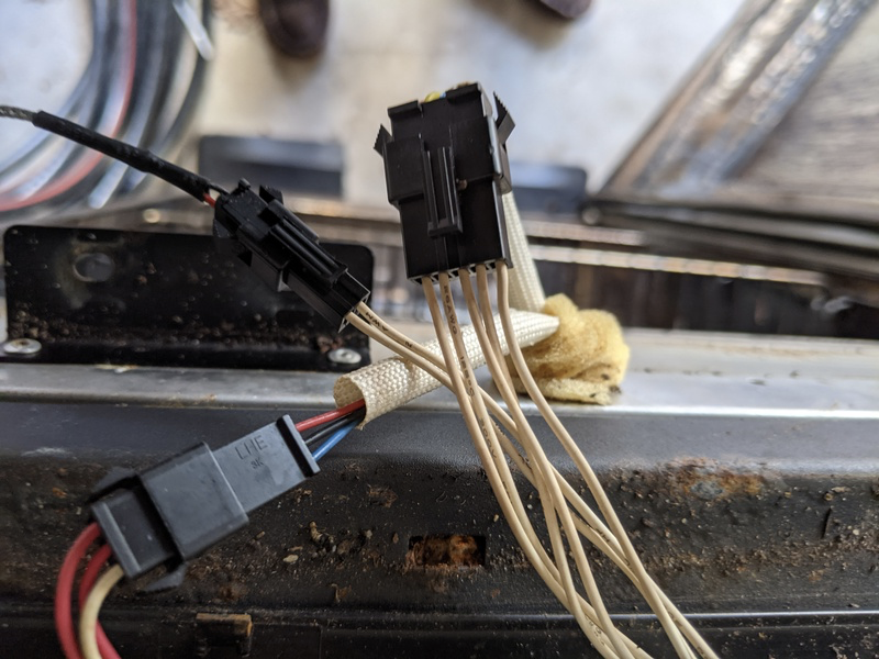
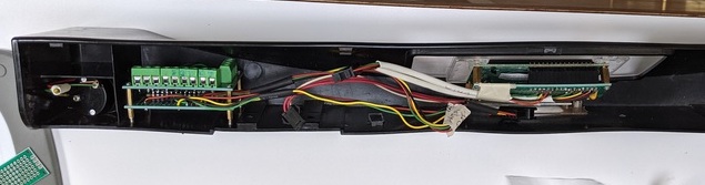
Removing the top front cover for the controller board shows three bundles of wire with three plastic Dupont style snap-on connectors. Here is a view from the top looking down at the front of the smoker
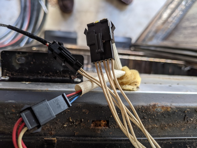
Wire Bundles
There are 2, 3 and 5 wire bundles.
- The 3-wire bundle does not go into the controller. It runs to the LED lights mounted within the top cover. These wires are thicker than the others. Two are red and one is white. These wires power the lights and my guess is they come from the power unit located in the bottom of the smoker. Likely they are relay activated by a control signal from the 5 wire bundle. I think this is done to lower the total current draw on the controller board. It does not appear in the controller schematic. I don’t know what the voltage is but I can ignore this bundle.
- NOTE: Looking at the power board schematic for a related model (the FCC site doesn’t have a power board schematic for this model) it appears that this lighting connector is a higher voltage than the controller board, perhaps 12 VDC unregulated.
- The 2-wire bundle comes from within the chassis and is insulated for high temperature. This is from the meat temperature sensor. These wires go into the controller board to become pins 6 and 7 of a seven pin connector on the board edge.
- The 5-wire bundle goes into the controller board as pins 1-5 of the 7 pin connector.
The controller board is housed within a plastic box sealed with what looks like an especially generous application of a silicone sealant. I speculate that earlier models may have had problems with “smokin’ in the rain” and they were determined that this model would not. The sealant hides the screws that need to be loosened to open the box so a bit of scraping is needed. Once the box is opened and the board removed you can see that the 5 pin and 2 pin wire bundles join to a 7 pin board edge connector.
A screen shot taken from part of the FCC controller board schematic shows the pin layout.
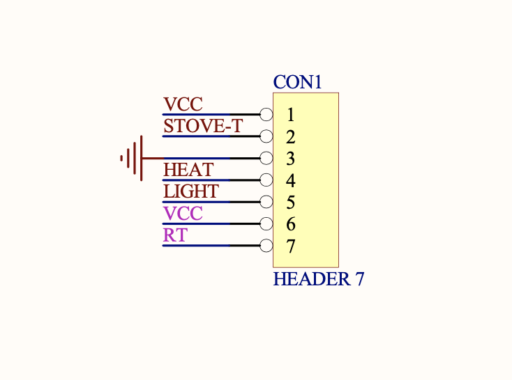
7-Pin Connector
            1:  +5V DC
2:  Stove Temp
3:  GND
4:  Stove On/Off
5:  Light On/Off
6:  +5V DC
7:  Meat Temp
8:  Light Power
9:  Light Power
10: Light Power
My interpretation is that HEAT and LIGHT pins carry digital output signals, HIGH and LOW, from the MCU to the power board. Looking at a similar model’s power board schematic leads me to think HIGH activates (closes) the relay and LOW deactivates (opens) the relay.
The STOVE-T and RT lines are likely the oven and meat temperature sensors respectively. From the FCC schematic these go into the MCU AIN0 and AIN1 pins respectively.
The FCC controller schematic and my inspection of the board indicate the MCU is a clone of the Toshiba TMP86FH09ANG. Documentation is available. The MCU has a 10 bit ADC converter like the Arduino. The value returned by the ADC is (VDD-VSS)/1024 where VDD is +5VDC (VCC) and VSS is 0 (GND). Given this, replacing the existing controller board with an Arduino seems feasible using the existing wiring.
Testing My Thinking
With all these wires and documents I wanted to be sure that my thinking matched reality. I decided to build bread boards to check this out with three goals:
- determine smoker base wiring (by creating a Dupont connector that mimics the OEM controller);
- determine OEM controller wiring (by creating Dupont connector with breadboard simulating the smoker)
- prototype the new controller (using the Dupont connector that mimics the OEM controller)
Below is a view of the Current System where the OEM controller board connects to the smoker body via two Dupont style connectors (pins 1-7) and the cabinet light LEDs connect to the smoker via a three-wire connector (pins 8-10).
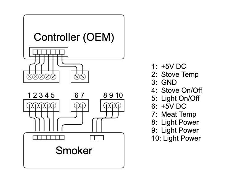
OEM Controller to Smoker
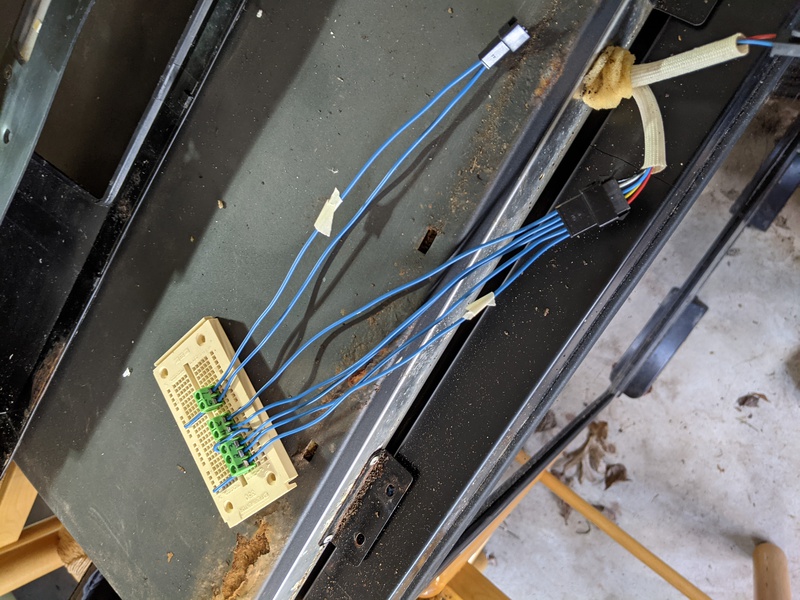
Next is a view of the diagnostic breadboard to be used to satisfy goals 1 and 3. Three Dupont style connectors are wired to duplicate the controller board connectors. At the breadboard the wires connect via screw terminals. When connected and the smoker is powered, these 10 pins at the screw terminals will be easily tested with a multimeter.
Connecting +5V to the stove and light on/off pins verifies that pins 4 and 5 activate relays. The heating element works! So does the light. Activating the stove heater in this way allows testing of the stove and meat temperature sensors.
Over time this board will become the prototype of the replacement controller.
NOTE that the pins 8, 9, and 10 may be at a higher unregulated voltage according to the schematic of a related model. The voltage must be tested before connecting these three pins to the breadboard to prevent potential damage.
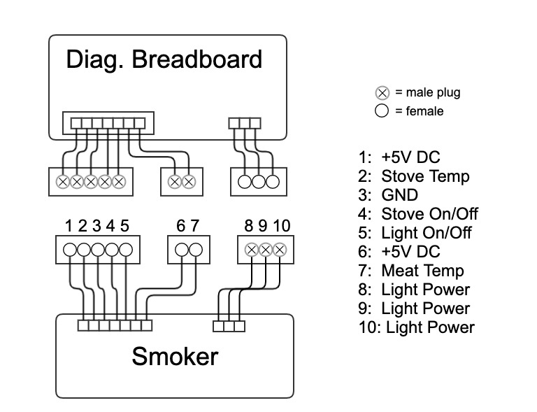
Breadboard to Smoker
In the following view, a diagnostic breadboard with a +5V power supply is connected to the OEM controller in order to verify that the pinout assignments match the available documentation (goal 2). The controller display does not work but the controller still functions verifying that the +5V and GND pins are correct. Manipulating buttons on the controller shows that the light on/off, stove on/off, and +5V to the meat sensor are correct.
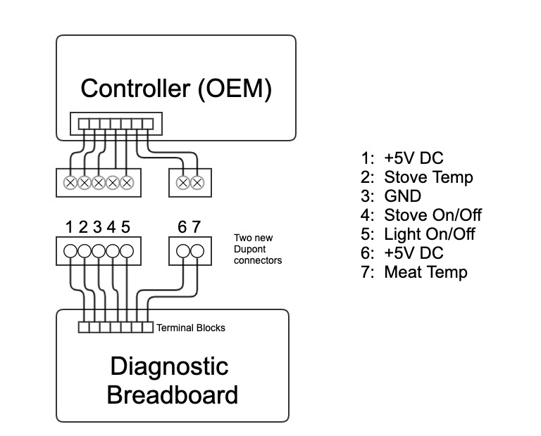
OEM Controller to Breadboad
Eventually I create a prototype controller and display unit on a pair of breadboards and a simulation of the smoker on another. I use this to develop and test the software. See the Appendix: Board Prototype for details.
Calibrating Thermistors
Sensors in a smoker are commonly either thermocouples or thermistors, the latter being cheaper and more common. Thermocouples have a direct linear relationship between the temperature and the voltage sensed by the microcontroller. Thermistors have a non-linear relationship and usually have an inverse relationsship, meaning the voltage decreases as temperature increases. This smoker uses thermistors for the oven and meat sensors.
The non-linear curve of a thermistor differs among products and its charactersistics are usually given in the spec sheet. If you can find one. I can’t.
For my breadboard prototype I copied example code that used the Steinhart-Hart method of linearizing a portion of the non-linear curve of a thermistor. The example code had used a thermistor matched to a typical room temperature range. I used this code with an spare thermistor from a floor heater. This code, my circuit, and this device matched well enough. Temperatures displayed by the board were within 2-3 degrees of a reference thermometer. The thermister was close to 1K Ohm at room temperature. My voltage divider used a 1K resistor to bias the signal to the Arduino’s 0-5V ADC range.
When I used this board on the smoker the results were not even close. Temperature was displayed as -460 F, which is absolute zero. As the actual temperature of the smoker increased the display temperature increased but it never came within 50 degrees of the actual.
I measured the resistance of the two thermistor leads at room temperature and they both were just below 300K Ohm. Now it makes sense. For a smoker you wouldn’t employ the same thermistor used in a floor heater.
So, how do I determine the Steinhart-Hart coefficients for the smoker? The manufacturer has abandoned this model and no support is available. I’ll have to figure this out by myself.
The Empirical Method
I used a diagnostic breadboard to test my design.
Divining Board
In order to generate data on thermistor values at different temperatures I started the smoker’s oven heating element by jumping the +5V supplied by the smoker on pin #1 to pin #4, the oven heater relay switch. I put a Taylor 3506 mechanical oven thermometer in the oven. When the temperature reached a suitably high value I shut off the heater, opened the oven door and measured temperature vs resistance at various points as the oven cooled down.
Note that later on I repeated these tests using the prototype board and got confusing results until I realized that the thermistor must be disconnected from the voltage divider circuit on the breadboard.
The Taylor 3506 is not very precise but it is reasonably accurate. I calibrated it in a Wolf oven. I had to make the measurements as the temperature hit round numbers on the Taylor’s dial as the oven cooled.
The numbers are used to calculate the Steinhart-Hart coefficints. Fortunately there is an online calculator that will produce a set of Steinhart-Hart coefficients which will replace the values I used in the test code.
See the calculator at thinksrs.com
First Test Run
For this run I looked in the box at the Taylor thermometer, waiting for the needle to hit a major division on the scale and then touched the multimeter test leads to pins 2 and 3 to get the resistance.
| Resistance (KOhm) | Taylor Temp (F) | (C) |
|---|---|---|
| 16.6 | 260 | 126.7 |
| 24.2 | 250 | 121.1 |
| 27.7 | 225 | 107.2 |
| 31.0 | 200 | 33.3 |
| 40 | 180 | 82.2 |
| 54 | 150 | 65.6 |
| 66.7 | 123 | 51.7 |
| 75 | 110 | 43.3 |
Note that the Taylor was hung from the front of the middle shelf. With the door open, it likely cooled faster than the thermister. Next time I will move it to the back of the shelf where it will be a few inches from the thermister.
Calculation of Steinhart-Hart Coefficients
The values entered:
| Resistance (Ohm) | Temperature (C) |
|---|---|
| R1=75000 Ohm | T1=43.3 C |
| R2=31000 Ohm | T2=93.3 C |
| R3=16600 Ohm | T3=126.6 C |
The Steinhart-Hart coefficient values returned by the online calculator are:
| S-H Coefficients |
|---|
| A = 4.265900724 e-3 |
| B = -4.298786796 e-4 |
| C = 26.29751169 e-7 |
The beta model values returned are:
| Beta Model |
|---|
| R(25C) = 111600.42 Ohms |
| beta = 2049.07 K |
I don’t currently use the Beta Model but may try that later.
When I used the A B C coefficients in the software I got an improvement but not good enough. So I tried another test run.
Second Test Run
For this run I made the multimeter test leads part of the breadboard so that I got continous readings of the resistance between pins 2 and 3. Now when I see the Taylor thermometer needle hit a major division on the scale I just record the resistance.
| Taylor Temp (C) | Temp-Taylor (F) | Resistance-Oven (K Ohm) |
|---|---|---|
| 162.8 | 325 | 6.24 |
| 148.9 | 300 | 11.5 |
| 135 | 275 | 14.4 |
| 121.1 | 250 | 19.5 |
| 107.2 | 225 | 23.7 |
| 93.3 | 200 | 30 |
| 79.4 | 175 | 37.5 |
| 65.6 | 150 | 49.5 |
| 51.7 | 125 | 67.1 |
Calculation of Steinhart-Hart Coefficients
The online calculator allows you to enter resistance and temperature values for the part of the resistance curve that you want to be most accurate and it returns coefficients for that range. As I understand this, the S-H algorithm will approximate a linear response within a defined range of the total curve. Making the range too large reduces the general accuracy. So I want to narrow the range for the most important values that the smoker will use. Say for salmon to brisket.
The values entered:
| R (Ω) | T (°C) |
|---|---|
| R1: 6240 | T1: 163.8 |
| R2: 19500 | T2: 121.1 |
| R3: 37500 | T3: 79.4 |
The Steinhart-Hart coefficient values returned by the online calculator are:
| S-H Coefficients |
|---|
| A = 7.804333668 e-3 |
| B = -9.836174642 e-4 |
| C = 46.15099199 e-7 |
The beta model values returned are:
| Beta Model |
|---|
| R(25C) = 836001.46 Ohms |
| beta = 4596.90 K |
Testing the Results
Now that I think I have divined the thermistor resistance curve and have S-H Coefficients for the part of the curve that I am interested in, I can update my software, Thermosetter.ino, and test its ability to get to a set temperature and stay there.
I did several runs, capturing temperature readings from both the Taylor thermometer and the software’s calculated values. Graphing the result shows that the thermistor model is good enough for a smoker.
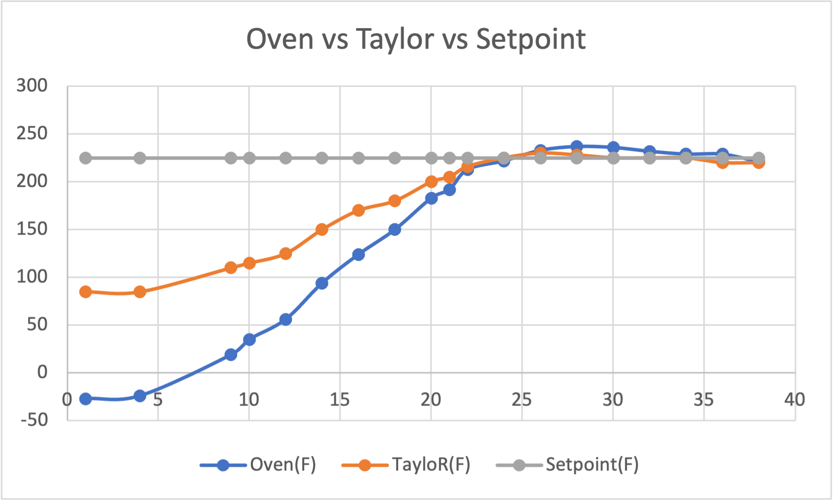
Graph of Oven vs Taylor vs Setpoint Temperatures
Constraints
Warning
Note that ELECTRICITY IS DANGEROUS. Do not attempt this hack without an understanding of the dangers involved in working with electricity.
Also note that I am not an Electrical Engineer so don’t take my word as gospel. I only provide inspiration, or perhaps entertainment. Verify every thing yourself.
Having said that, the smoker does have replaceable parts and that’s what this project entails: replace the stock controller head unit with an equivalent device.
Unknowns May Impact Goals
The goal here is to replace the low voltage control subsystem of the smoker unit. Other parts are assumed to be functional such as the high voltage power control board, the heating coils and related wiring. However these may need replacing using OEM parts. Some OEM parts are still available at the time of this writing. If no longer available, well, that’s another hack.
Size Constraints
The existing control unit fits within a 150mm x 55 mm opening in the console, i.e. the top-front section of the smoker housing. The unit is sealed and weather proofed. The housing has a diagonal, almost triangular cross section in the middle that limits the size of the replacement components. However there is room to spread out horizontally beyond the console opening.
Weatherproofing
The smoker in its current state can be left out in the elements, perhaps, with no effects on the electronics. On the other hand I have this unit because it doesn’t work. Who knows why?
The changes for this hack intended to achieve weather resistance by using suitable sealing and the use of components rated to IP66 or IP67 levels of ingress protection. However some IP rated components are too bulky to fit. So I have to compromise. The result will require the use of a weather tight smoker cover if left outside. I do not suggest smoking directly in the rain.
I also have a propane powered box smoker and with that one I can get it wet with impunity. But this device has a power cord attaching it to high voltage household current. Just like a fan. Use common sense. Keep it dry.
Wiring
The goal is to replace the head controller unit without rewiring the whole smoker. The composition of the wiring varies among models and there is no schematic that I have found that officially applies to this model. However there are FCC filings by the manufacturer that apply to a model that uses the same microcontroller as my model. See discussion of FCC docs in the Referenced Documents section. So the box and its internal connectors have to be examined before finalizing the design. To this end I have created testing breadboards. See section Divining the Wiring for Model 20070512.
Other Things
Note also that this product model has been recalled due to a fire hazard. It seems that the wood feeding tube, which allows wood to be added to the fire box, may in some cases drop wood onto the heater coils resulting in uncontrolled burning, possibly causing the smoker door to burst open. See US-CPSC recall notice. Recall number: 13-241. The CPSC Manufacturer contact is Masterbuilt Manufacturing at (800) 489-1581 from 8 a.m. to 5 p.m. ET Monday through Friday or online at www.masterbuilt.com and click on Contact on the top right hand corner of the page for more information.
A remedy is or was available available from the manufacturer as a user installed kit. It is unknown if the remedy kit is still available or if it has been installed in this unit. Retro fitting a newer fire box/feeder tube is possible.
Modes of Operation
Support documentation for this model is not available on the Masterbuilt website. The following was taken from the operational instructions in a manual for a related model: 20077815.
The controller unit has the following operational modes. Not all of this will be replicated in the replacement controller:
Description
- Power On button controls power for the controller unit.
- Set Temperature. Sets the threshold for operation of the heating element. Presumably this set the center of a band of temperatures for on and off of the heating element.
- Press ON button.
- Press SET TEMP button once. LED display will blink.
- Use +/- to set temperature.
- Press SET TEMP button again to lock in temperature. Heating will not begin until timer is set.
- Set Timer. Sets the duration of an operating session in hours and minutes.
- Press SET TIME button once-LED display for hours will blink.
- Use +/- to set hours.
- Press SET TIME button again to lock in hours. The minutes LED will start blinking.
- Use +/- to set minutes.
- Press SET TIME to lock in minutes and start cook cycle.
- Heat will turn off when time has expired.
- Meat Probe. Changes the LED display to show the current temperature of the meat probe. Releaseing reverts to previous display (session time or box temperature).
- Insert meat probe into center of meat to get most accurate reading.
- Press and hold MEAT PROBE button-LED display will show internal temperature of meat.
- Once MEAT PROBE button is released-LED display will return to set temperature or set time.
- Light
- Press LIGHT button to turn light on.
- Press LIGHT button to turn light off.
- Reset procedure
- If control panel shows an error message, turn electric smoker off, unplug unit from outlet, wait ten seconds, plug unit back into outlet, then turn electric smoker on. This will reset control panel.
- Indicator LEDs
- LED for power on to the controller
- LED for power on to the cooking element
Discussion
For the current system, setting time and temperature must be available during all modes of operation so that changes can be introduced to the running process.
Feedback information, temperature of the smoker box and temperature of the meat via the meat probe, must be communicated back to the controller unit and be displayable so that the user can make changes to the time and temperature settings.
The timer defines the start and duration of a cooking session. If there is no time on the clock the heating element will be off. If there is time on the clock the controller will attempt to reach the target temperature by turning on the heater element. Once the target is reached the heater is switched off. The user is expected to know how long the cooking session will be. Anyone who has smoked meats will recognize the so called stall effect when the meat refuses to rise to a higher temperature for a prolonged period. This makes time estimation difficult is not impossible.
Because the heated air mass exhibits inertial delays (hysteresis), the oven may over or under shoot the target temperature. This requires some sophistication in the control logic to minimize overshooting and undershooting the set tmeperature. It is unknown how the current system deals with this.
The controller signals on and off states to an electro-mechanical relay simply using 5 VDC to turn on the heater and 0 VDC to turn it off. Such a system is limited in how fast these on and off cycles can be.
Much of the complexity of the system is due to the limited display capability of the control unit. It has a singls 4-digit, 8-segment display. It can display set time, elapsed time, set temperature, oven temperature, meat temperature. But only one of those parameters at a time. To multiplex the display across parameters requires multiple switches. This complexity is eliminated if the display unit can display multiple parameters at one time.
Support Environment
The manufacturer has withdrawn support for this model. Calling the 800 number in the manual directs you to the website for support. I filed a support case and received a boilerplate response indicating that the product has reached end-of-life. Some parts are still available from the manufacturer and also from a third party. Unfortunately, there are no more replacement controllers.
Essentially you are on your own.
- Changes
4 Changes
Description of Desired Changes
Changes Considered But Not Included
Justification of changes
- Controller LED display is defunct, making the smoker unusable
- Replacement OEM controllers for this model are no longer sold
- Newer OEM controller models not compatible
- Hacking is fun
- I can do this.
Description of Desired Changes
A new controller based on an Arduino MCU can be dropped in as a replacement for the OEM controller. The existing pinout of the OEM controller will be preserved.
The existing control unit opening in the smoker’s console cover will be fit with a new plexiglass panel cut from 1/8 inch sheet behind which are the new electronics.
The user interface will change considerably. The existing user interface involves many button switches to manage control parameters such that a single four-digit seven-segment LED can be multiplexed over these parameters. The same display is used to show a count-down timer, setting of the count-down timer, setting of the target oven temperature, the current oven temperature, and the current meat temperature. There are physical button switches for selecting each parameter as well as increment/decrement buttons for setting the selected parameter.
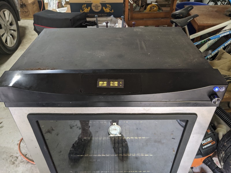
The new interface is much simpler. The display module is a 16×2 OLED display that shows elapsed time, target oven temperature, current oven temperature, and meat temperature in a compact two line format. The buttons are replaced by a single dial that combines on/off and target temperature selection. Note that on/off refers to the display. The controller is powered whenever the smoker is plugged into the household mains circuit.
Some functionality of the original system will be dropped in favor of simplicity.
- the system will not automatically stop cooking when a countdown timer expires
- the system will not automatically stop cooking when a meat target temperature is reached
The user will have to monitor the progress of cooking and stop the system manually. The count-down timer is replaced with an elapsed-time counter that begins when the unit is powered up and runs continuosly.
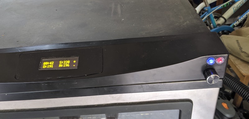
The display is two lines of sixteen characters.
            ----------------
 HH:MM  S:999 *
 O:999  M:999 =
----------------
First Line:
- HH:MM is the elapsed time counter
- S:999 is the set temperature
- Heating indicator
- ‘*’ Heat is on
- ‘<‘ Heat is off
Second Line
- O:999 is the current oven temperature
- M:999 is the current meat temperature
- Standby indicator
- ‘=’ Standby is on
- ‘.’ Standby is off
The Standby state is active when the set temperature is below a threshold value of 170 F. The oven heater is always off when in Standby.
Priorities Among Changes
The changes preserve some but not all of the features of the original system.
The highest priority is the ability to set a given temperature and have the system maintain that for hours at a time.
Ease of use in setting and changing the set temperature is also a high priority. This includes the user interface: the display and the temperature setting dial.
The system should minimize overshooting set temperatures due to sensor inaccurracies as well as the hysteresis of the smoker body.
Weather proofing is a lower priority due to the difficulty in achieving it and the fact that this is a hack and not a consumer product. The changes have not been tested for weather resistance.
Changes Considered But Not Included
PID Controller
There is a lot of discussion on smoker social media regarding the superiority of Proportional, Integrative, Derivitive (PID) control algorithms for smokers. While PID is clearly superior for industrial control applications it is not necessarily called for in an electrical smoker. The difference between superior and good enough may not be noticable in the finished product. Consider that wood fired pit smokers produce awesome ‘Q’.
To use a PID controller in this smoker would require bypassing both the power control unit and relay and re-wiring the heater element to be supplied directly from the PID controller. This is feasible, and a good choice if your smoker has blown its power board along with the controller board, but that will not be attempted here in favor of a less expensive approach.
The main impediment to precise temperature control in this smoker is due to the power supply board design. It toggles the heating element using an electro-mechanical relay such that the power is either full on, at 1200 watts, or full off. Cycling the relay in sub-second timing will cause the unit to fail prematurely so that precludes using Pulse Width Modulation (PWM) to provide power control. To properly use the PID algorithm requires PWM and a Solid State Relay (SSR) to do the power switching. Some PID controllers have this built in but here you must bypass the power control board.
A second impediment to precision is that the cooling of the unit is passive. My testing shows that the smoker takes three times as long to cool as it does to heat.
In order to improve the temperature control, the temperature modulation algorithm will approximate some aspects of PID control in a simple way.
Automatic Shut-off
I am not convinced that the value proposition for an automatic shutoff justifies the complexity. A common occurrance in smoking meats is the dreaded stall. This is a temperature plateau where the meat gets to a temperature and stays there for a long indeterminate time. A countdown timer shutoff is useless in this case as you cannot predict the finish time and you do not want the unit to shut off. A meat temperature shutoff is a bit more practical but do you really want the smoker to cool down with your meat still sitting inside?
Wireless connection to a smartphone app for control and monitoring
This is a compelling feature and could be achieved by using an Arduino model that has Bluetooth and/or WiFi capability. However that entails writing apps for Android and iOS. Too much work for this go around.
Serial connection to OLED module
This implementation uses the 4-bit connection option of the OLED module. There are some issues, discussed elsewhere, that can be mitigated by using the serial connection option.
- Concepts for the Proposal
5 Concepts for the Proposed System
Background, Design Objectives, and Scope of the Effort
Controlling Temperature with an Arduino
The Arduino is a micro-controller that runs just one program loaded into its flash memory. Adding or updating a program is thus referred to as flashing the program.
The Arduino micro-controller has a variety of input and output pins that can be used to receive information from sensors and produce changes in the environment via actuators. These I/O pins are characterized as analog or digital as well as input or output giving four configurations per I/O pin.
Digital pins have two states defined as HIGH and LOW. These map to the maximum and minimum voltages for a particular Arduino model.
Analog pins accept as input continuously variable voltages in the range of 0-5 VDC (or 0-3.3 VDC depending on the Arduino model). When configured as input the pin uses an internal Analog to Digital Converter (ADC) circuit on the Arduino to convert the voltage into a digital value in the range of 0 to 1023. Application circuits are required to map the voltage of the signal into this range. The approach used in this hack is to create a voltage divider circuit for each sensor. The temperature sensor, a thermistor, provides part of the voltage divider and a board mounted resistor provides the other half. Connecting the thermistor to a voltage source produces a voltage proportional to the resistance of the thermistor. The board mounted resistor is selected to bias the thermistor so that its “sweet spot” produces an ADC value near 512. For a smoker the sweet spot temperature is around 225F. I smoke salmon around 180F and finishing a brisket might go to 300F, maybe 350F. Outside of this range is of marginal interest.
Thermistor Concerns
Thermistors produce a variable resistance, not a voltage. However connecting a fixed voltage source, say 5VDC, to one lead will produce a variable voltage on the other lead. Thiat is how this smoker has been designed.
Using thermistors introduces a complexity for inferring a temperature from a voltage. The thermistor’s relationship between temperature and resistance is not linear. But I do not have an equation that describes it. Each thermistor product will have a different curve. The common engineering solution for this it to use the Steinhart-Hart technique. What that does, in my limited understanding of it, is to make an approximate linearization of a small portion of the curve. The technique produces a set of three coefficients that are used in a fixed formula to calculate a temperature. The coefficients are given in the spec sheet, if you have one. Or you can derive them empirically. I took the empirical approach. See Calculating Thermistors in the Current System section.
So for a smoker the “sweet spot” temperature is a band around 225F. The wider we make this band the less accurate the temperature calculation will be. This aspect is a software only configuration. Once the voltage divider is soldered on the board, the S-H calculation can be fine tuned using a breadboard to simulate the smoker where potentiometers simulate thermistors.
Is PWM applicable?
Arduino may also produce analog outputs. However the output is not a true analog signal. It uses a digital technique known as Pulse Width Modulation (PWM) which produces a high frequency on and off pattern providing effective power proportional to the time spent in the on state. Many, but not all, analog devices can accept this in place of a true analog signal. The pins labeled PWM may be used as analog outputs.
However, the Smoker Controller will not use these PWM outputs because none of the connected devices can make use of it.
Digital outputs will work better with the existing hardware. The existing power supply board, which will not be replaced, uses an electro-mechanical relay to switch the heating element on and off. This kind of device requires a relatively long cycling frequency to protect the hardware from failure. The heating element can be turned on for a few seconds and off for a few seconds without causing undue wear. In contrast, a PWM output will cycle at hundreds of times per second. A replacement power supply board using a Solid State Relay (SSR) would be required in order to use PWM as a control strategy.
User Interface
In order for the system to manage the temperature within the smoker the user must be able to tell the system what temperature to maintain. The Smoker Controller Hack provides a user interface (UI) consisting of a single OLED display with two lines of sixteen characters. Additionally two LED status lights, a potentiometer and a switch make up the UI. The UI functions:
- Setting the target temperature
- Display of the target oven temperature
- Display of the actual oven temperature
- Display of the actual meat temperature
- Controlling the light in the oven
- Turning the display sub-system on or off
- Indicating when the heater element is powered
- Indicating when the system is in standby mode
The Smoker Controller will affect its environment via the existing Masterbuilt high voltage relay which powers the heating element. The relay unit, located in the base of the Masterbuilt model, is distinct from the head controller and will not be replaced. This relay has two states: on and off. These states are defined by a digital pin signal from the Arduino controller unit. Software will turn the heater on or off depending on sensor input evaluation.
How Good Can it Be?
There is debate whether an on and off heater protocol can ever produce the perfect smoking result. The issue centers on maintaining an even temperature within the oven. There are continuously variable controllers which can maintain a more even temperature using a algorithm known as Proportional, Integrative, Derivative (PID). Doing that in this smoker would require replacing the Masterbuilt power relay unit with one that can be driven by a higher frequency PWM signal. That is beyond the scope of this project. An on and off heating protocol in the seconds scale will be used and digital output pins will be used to control the heater.
The hysteresis of the whole system results in the temperature of the box rising for minutes after the heating element is shut off. This presents a challenge. The heating element gives off heat to the air in the oven box which in turn gives heat to the metals within the box. Turning off the heat results in the metals giving back some heat to the air, raising the temperature. Obviously turning off the heat before the set point is reached will improve precision. But how far before? This is like docking a boat. You have to turn off the motor before you hit the dock but how far?
There are some techniques that will improve the effectiveness of any heating strategy. One is averaging the readings to smooth out changes due to noise in the electrical circuits. Adding capacitors at various places in the circuits will also reduce noise and make readings more consistent. Another is to use part of the PID principles to create a band of acceptable temperatures around the value set by the user. Rather than calculate the integral of multiple small temperature changes to get a precise estimate of the temperature curve, we will use the slope of a single longer temperature change to get a gross estimate of the curve. This value, modified by a fudge factor, will be used to expand or contract a band around the set temperature. When the temperature enters the band from below, during heating, the heater is shut off. When entered from above, during cooling, the heater is turned on. Empirically it seems that this oven heats about three times faster than it cools. The fudge factor mitigates this making the upper band thinner than the lower band. During initial heating the slope is large and the band is wide. As time goes on the slope is more gentle and the band narrows. However at any time the heating element is either producing 1200W or zero. The hysteresis of the whole system combined with active heating and passive cooling limits precise control.
Circuit Board Design
The plastic housing for the existing controller has an irregular shape giving the internal space a sloping, almost triangular side profile. This limits the size of the replacement controller. However there is ample room to spread out horizontally. I cannot replicate the miniaturization of the original board and its waterproof housing. Instead soldered components are placed on three circuit boards:
- Arduino Interface Board (AIB)
- Smoker Interface Board (SIB)
- Display Interface Board (DIB)
The AIB and the SIB will be stacked together. The DIB will attached to the OLED module and connect to the AIB via an 8-wire bundle.
The DIB has a 16 pin female connector to mate with a 16 pin male connector on the display module. The DIB has two 4-wire bundles (phone wire) soldered to the 16 pin connector and terminated into a single 8-pin Dupont connector. The DIB and SIB connect via this Dupont connector.
Software Design
ThermoSetter.ino
This program is an outgrowth of the software developed to divine the wiring of the system. It is organized following the so-called Super Loop software pattern. There are several tasks that are to be performed with each iteration of the Arduino loop function. The tasks are organized as blocks of code. Each task has a distinct time interval that is checked with each loop to determine if the task is to be performed or not. If not the loop is exited. With this pattern the tasks must be organized in the sequence of increasing time interval. Also with this pattern the use of the delay() function is to be avoided for anything greater than a few milliseconds.
Powering the Arduino
The existing smoker has a functioning power board which supplies the controller board with 5 volt DC power. There is a five pin connector and a two pin connector that will be reused to connect the replacement controller board to the smoker.
The Arduino Nano Every model to be used in the replacement controller can be powered by several means:
- USB mini-B plug (5V DC),
- Vin pin #30 (7V to 20V DC),
- +5V pin #27
The first two utilize the Arduino’s onboard regulator. The third bypasses the regulator and assumes the source is a regulated supply. The existing smoker specification provides regulated 5V, although the quality of this is unknown. It has been measured between 4.5V and 4.8V.
Description of the proposed system
The basic idea here is centered around the 7 wires that connect the smoker to the control board. Replacing the control board entails duplicating the functional behavior of the 7 wires.
The diagram below shows the inferred function of each of the 10 wires emanating from the top of the smoker cabinet. Three of these are power lines to the smoker lighting unit and are not changed. The other 7 have been traced to components under control of the OEM controller.
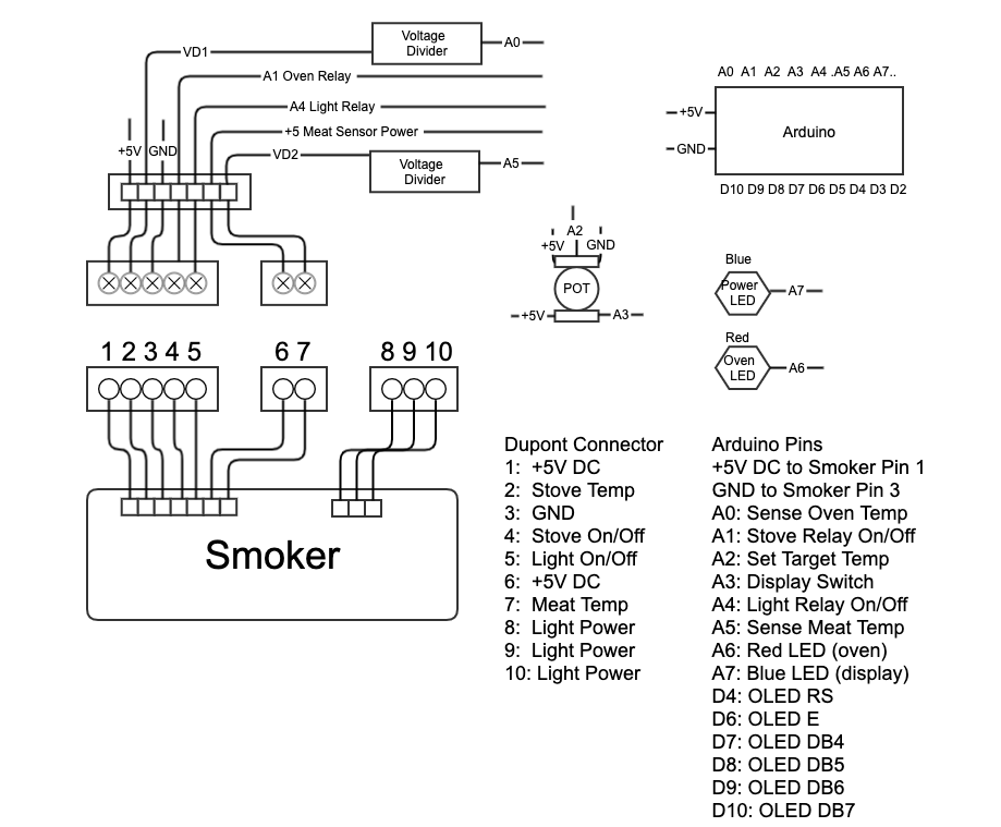
Smoker to Arduino Connections
The replacement controller has three functional areas that are physically implemented as distinct modules:
- Display module
- Smoker interface and conditioning circuits
- Arduino mount and its interfaces to the other two
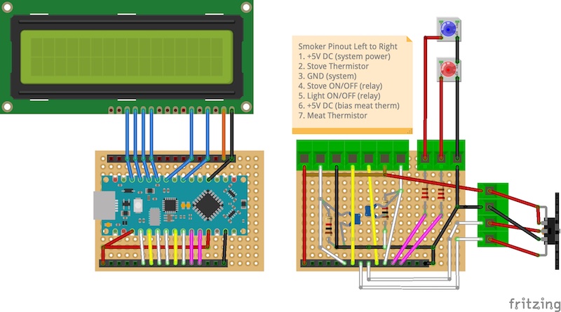
Below is a Fritzing model: 
Ideally these modules would be stacked via 16-pin connectors. However the internal space of the smoker console does not permit this. The compromise has the display mounted onto a central plexiglass sheet and the other two modules stacked off to the side, connected via an 8-wire bundle.
Completing the user interface, the temperature setting potentiometer and switch is mounted at the right side front of the console. Above it are two LED indicators for display status (blue) and heater status (red).
Operational policies and constraints
The relay controlling the heating element is a physical relay, not an SSD. As such its on and off cycling frequency is constrained in order to prevent unit failure. The specs for this unit are not available but similar ones are, suggesting a minimum frequency of about 3 seconds on 6 seconds off. This will be under the control of the software so that the user need only set the target temperature.
The existing smoker has gone to lengths to make the system relatively weather resistant However this replacement is, after all, a hack. It will require that a cover be used to keep the system dry and that it not be operated in the rain.
Modes of operation
Plugging the smoker into a house power activates the smoker’s power board and the controller board. The smoker’s elapsed time counter is activated when it is plugged in. The heating element is off in this state. The user interface has a dial with an on/off switch. This switch controls the display not the system power. Turning off this switch turns off the display. Turning it back on resets the display and this may be used to clear it. The elapsed time continues even when the display is off.
If the display shows odd characters due to electrical interference, turning the display off then on again may correct the display.
New User Interface
The dial sets the target temperature for the smoker. The dial ranges from 150F to 350F. When the dial sets a temperature below a threshold, currently 170F, the system is in standby state with the heating element off. Turning the dial past this threshold allows the heating element to turn on if the oven sensor reads below this temperature.
There are two LED lights on the front of the console above the temperature dial. The blue light is on when the dial switch is on. The red light is on when the heating element is on.
It is possible to power up the smoker while the dial is at a high temperature position. In this case the heating elment will go on and heat the smoker. It is good practice to turn the dial into the standby zone or all the way to the off position before plugging in the smoker.
Support environment
This is a hack, there is no support environment. You are on your own. 6. Operational Scenarios
6 Operational Scenarios
Power and Temperature Setting
To power up the unit it is plugged into a 15 Amp outlet just like the original unit. When plugged in the controller is fully powered. The setting dial also contains a twist on/off switch. If the setting dial is in the off position the display will be off. Switching the set dial to the on position will activate the display. Initially the heater will be off.
Two indicator lights above the dial indicate that the display switch is on (blue) and the heating element is on (red).

User Interface
Set a temperature target by rotating the dial clockwise. The display will show the setting temperature as “S:” and three digits. If the set temperatures is below a software defined threshold, currently 170 F, the unit goes to “Standby” mode where no cooking will occur. The heating element will stay off when in the standby state. Settings above the standby threshhold will activate the heating element until the temperature approaches the set temperature. The heating element is shut off before the set temperature is reached so that the oven can “coast” up to the set temperature without overshooting it.
Producing Smoke
I have not tested this smoker’s ability to produce a good amount of smoke from the wood chips loaded into the smoking pan. With other smoker’s I have used there is a reluctance to produce good smoke when trying to limit the temperature of the box to low temperatures. For example smoking salmon is best at around 180 F but wood wants a higher temperature in order to smoke. So sometimes you have to start up the smoker hot, then lower the temperature, perhaps opening the door to cool it off. And this lets smoke out so there is an art to this practice. Good luck. Have fun. If all else fails, have a beer.
Display Reset
This hack occasionally runs into a problem where the display unit prints garbage characters on the display. This can be caused by electromagnetic interferance disrupting the synchronization between the Arduino and the display unit. Most often this can be eliminated by switching the set dial off then on again. The set temperature will have to be reset but the elapsed time will be preserved. If this does not work after trying several times, unplugging then plugging the smoker will work, although the elapsed time will be lost.
Water Exposure Concerns
The smoker, after these modifications, will not be as resistant to weather as the original unit. The unit should be protected by a water proof cover when it is not in use. During active use the unit should be protected from rainfall by a roof or canopy.
This hack replaces the controller unit and introduces some exposure to the elements that had been addressed in the OEM controller. The rest of the smoker, the power board and the heating element, are as weather resistant as they ever were.
I do not recommend using an electric smoker in the rain.
- Summary of Impacts
7 Summary of Impacts
Basically with this hack you can desregard most of what is in the OEM User manual. Refer to the Operational Scenarios section for operating instructions. This hack provides a much simpler operational procedure.
There is no wireless remote in this hack.
There is no longer an automatic shutoff. 8. Analysis of the Proposed System
8 Analysis of the Proposed System
Summary of Improvements
The scope of the hack is not necesarily the improvement of the smoker. The intent is to restore operation. The simplification of the user interface can be viewed as an improvement or disadvantage depending on how important features like auto shutoff and remote control are to the user.
At this point I can’t tell if the smoker makes a better briscuit or not. I never used the original and have only tested temperature settings at this point. Time will tell.
My point of view is that having all of the operational parameters display on one screen and elimination of the buttons on the console is a human factors improvement.
And of course, making this hack is its own reward.
Disadvantages and Limitations
Disadvantages of Plexiglass
Plexiglass is a brittle material to work with. It is prone to forming stress cracks during assembly. The 1/8 inch sheet used was just the right thickness to insert into the opening of the console but the stress of assembly introduced new cracks at a time when much effort had been invested.
Lacking a laser cutter, I cut the pieces by hand and fitted them by filing and sanding. If possible, a laser cutter will make it feasible to cut several of each piece to have backups.
In order to attach the display module using standoff screws, I had to thicken parts of the sheet by gluing additional plexiglass strips onto the main sheet. This worked well. However I should have used a press to eliminate bubbles in the glue. When pressed hard the two sheets bond so as to be completely transparent. But any air gaps will impact the appearance. Gaps between the sheets cause reflections that highlight the bonding. I decided to spray paint the backside of the sheet, giving the front a nice glossy finish. However the bracing pieces, glued imperfectly, marr the finished look. So I spray painted the front. Note that solid colored plexiglass is available and that would obviate these problems.
Infrequent OLED Display Problem
The OLED display unit supports three interface wiring options:
- 8-bit
- 4-bit
- serial
For this implementation I chose the 4-bit wiring option. This has the advantage of simple wiring but it has a disadvantage in needing tighter synchronization between the display unit and the micro controller. Each byte sent over the interface is sent as two 4-bit packets rather than as a single 8-bit packet. If an electrical disturbance affects the Enable line it may cause the two chips to lose synchronization and become confused as to which half of a byte is being sent. Once this occurs the two chips do not have a protocol to detect the problem and re-establish synchronization. This is characterized by the display of random characters on the display.
Like this:
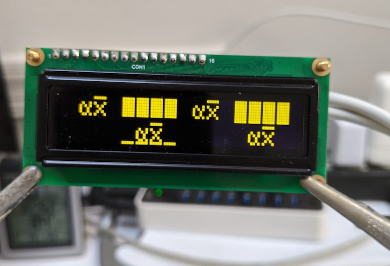
display_fail.jpeg
To mitigate this, the on/off switch is used to signal the software to send the display-off command when the switch is off and turn the display on when the switch is on. This seems to work. If this does not work then unplugging and replugging the smoker will reestablish sync but you will lose the elapsed time.
When I started out with the design I thought the boards would be stacked giving only very short wire runs. Later, I realized the space was too small to accept stacked boards. The new layout has a 6 inch wire run between the MCU and the OLED unit which may pick up electrical interference. I added a capacitor across the Vdd and Vss lines but it may be too small.
Lesson Learned: It may have been a better option to use the serial interface.
Alternatives and Tradeoffs
No Wireless
I simplified my task considerably by not including a wireless capability. To have wireless capability I would have had to write an Android and perhaps an iOS app. ‘Nuff said.
So the only way I can get debugging information out of this system is via USB serial. To connect the micro USB on the Arduino Nano Every requires removing the console from the smoker. Installing a USB jack into the console cover is possible but would increase the risk of water intrusion. If I had telemetry I could make software improvements based on in situ observation.
PCB Design
The physical design is dictated by the perf-board PCB that I had available. The plexiglass sheet on which the OLED display board is mounted is large enough to contain all of the circuits needed by this system but this would not have worked with the boards I had. The result is the boards are distributed within the console piece and have long wire runs than I would have liked.
Parallel vs Serial Interface to OLED
As noted in the Disadvantages and Limitations section, the 4-bit parallel interface to the OLED in conjunction with long wire runs exposes the system to interference that may disrupt the synchronization needed for the 4-bit interface. This became apparent after the boards were soldered. I think this will work well enough but only time will tell. Next time I will try the serial approach. 9. Appendices
9 Appendices
A. Glossary
B. Board Prototype
C. Board Design
D. Board Assembly
E. Display Wiring
9a. Glossary
A. Glossary
- Hysteresis
- With regard to heat, the phenomenon of the temperature in the smoker continuing to rise well after the source of the heat is removed. Like a boat on water drifting toward the dock after the motor is shut off.
- MCU – Micro-Controller Unit
- A micro controller is a computer device intended for simple specific applications. It does not have the power or complexity of a general purpose computer.
- OEM – Original Equipment Manufacturer
- An adjective for parts added by the original manufacturer. In my useage an OEM part is anything that I did not supply. I could have called it NMS (Not My Stuff).
- OLED – Organic Light Emitting Diode
- There are many kinds of OLED devices but I am using the term to describe the display module. This particular OLED display is packaged to mimic a well known Liquid Crystal Display module. This enables me to use the LiquidCrystal library for the Arduino.
- PID – Proportional, Integrative, Derivative
- An algorithm used to control industrial processes. See this Wikipedia article for a detailed explanation.
- PWM – Pulse Width Modulation
- A digital technique for simulating an analog output by periodic pulses of full power interspersed with periods of no power.
- SSR – Solid State Relay
- A switching device capable of high frequency cycles of on and off. Often used with Pulse Width Modulation.
- TBD – To Be Determined
- I can’t know everything. I’m working on it.
- TODO – Tasks remaining to be done.
- There should not be any of these left in the document.
- UI – User Interface
9b. Board Prototype
B. Board Prototype
The design of the controller replacement required the creation of a breadboard prototype. To do this I mocked up a design using the Fritzing drawing tool.
Proto Drawing Using Fritzing
I had a hard time with Fritzing but it was worth it in the end. If you set it up correctly you can click on a wire and see graphically how it is connected to other parts.
Originally I wanted to stack these boards using PCB pin headers to communicate between layers. Unfortunately, the space within the smoker console is too small due to its tapered design. But this is not a problem for the breadboard prototype.
This prototype also required the breadboarding of a simulation of the smoker. The smoker contains another board, that I was not replacing, that performs power supply and switching functions. The smoker is in the garage and I did not want to stand there while building a prototype controller. I did have to verify the electrical properties of the power/relay board before I went into design. So having done that, I can now, in the comfort of my project room, create a simulation of that board.
Here is a picture of my prototype and test rig:
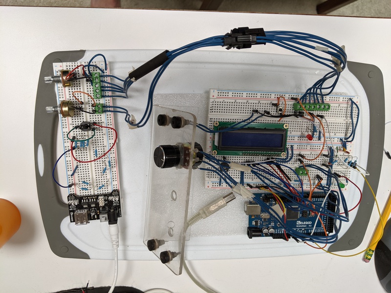
Prototype and Smoker Simulation
I like to use old plastic cutting boards as a work surface. This was a big help when it came time to carry the prototype to the garage for test runs.
The smoker power board simulation (on the right) uses a 5VDC power module to supply power to the Arduino over the 5-pin Dupont connector wired to a terminal block. The power and ground wires connect to the board power and ground rails. I attach the Arduino’s +5V and GND pins to the power rails of the breadboard and program the Arduino sketch to indicate that external power is used. The power rail is also connected to the AREF pin so that the analog input pins for the thermistors will have the correct voltage reference for the ADC subsystem to work.
The thermistors are simulated via two potentiometers allowing me to vary the voltage on the Oven and Meat temperature wires.
These boards are a bit messy because my thinking evolved as I encountered issues. I did not want to start over because my goal is not to build a breadboard but rather a set of PCB boards.
The breadboarding effort is invaluable in that it enables me go to the garage, connect the Dupont pins to the smoker, and start it up. At first I did not know anything about the thermistors, or even if they were thermistors. I had to determine their parameters empirically. 9c. Board Design
C. Board Design
The boards are built using perfboard PCB blanks. The 14×20 pin boards that I have are just the right size to fit into the ends of the console piece. The console is tapered in the middle where the OLED board goes but square in cross section at the ends. Two of these sheets with standoffs can be stacked within this space. The stacked boards are connected with 16-pin headers. The display board and the smoker power board both connect to the boards via wire bundles with Dupont connectors. Terminal blocks connect the smoker wire bundle with the Dupont connector to the board. Also connecting to terminal blocks are the 5-pin potentiometer/switch and two indicator LEDs.
This photo shows the three board design. The board containing the conditioning circuits and the terminal blocks is blank in this photo.
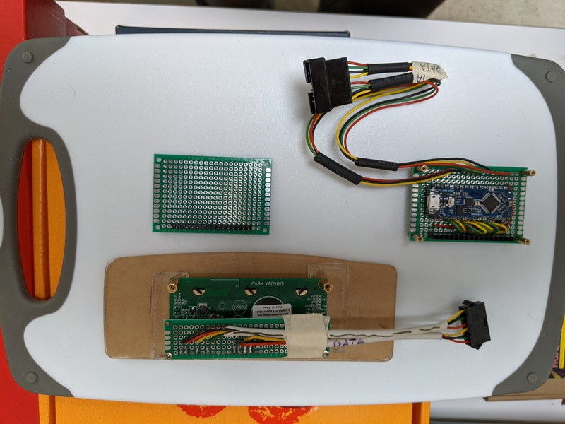
The Three Board Solution
Here is a test assembly.
Test Assembly
This is all new to me. I am a retired software guy. Hardware for me has long been plugging in boards and turning a few screws. Soldering? I don’t know. There are a lot of connections to plan before I heated up the soldering iron. In software undoing a blunder is much easier than redoing a board.
So I looked around for planning tools. Fritzing is great for breadboarding. There is a PCB tool in Fritzing but I can’t make it work for me. I didn’t want to go on a buying spree, searching for the right tool. In frustration, like I always have done, I got my coding stick and a pad of graph paper and drew cartoons. Wire graphs.
In order to layout the connections between the components I created three wire graphs on paper. Each graph is marked in the same convention as the perfboard blanks. In landscape view the rows are numbered from 1 to 14 and the columns are lettered A to T. Additional annotations were made to show connection details. The annotations are a little obscure but they make sense to me. I’ll try to explain them.
- Pin headers are drawn as squares where they are soldered to the board
- Wires are dots where they are soldered in
- PCB traces are drawn as thick lines
- Wires connecting dots are either drawn as thin lines when they would not clutter the diagram or they are represented as letter and number cartesian references for their terminal ends
- Wires that terminate in connections to a pin header are not soldered to the bottom of the board. They are soldered on the top where the pin header is soldered. The wire end goes into an adjacent cell and makes a U-turn coming out the adjacent cell so it can be soldered to the pin header. This is drawn as a C shape with two dots.
- Additional notations in the margins identify external references or color of a wire. N.C is not connected.
Wire Graphs
The Smoker Interface Board (SIB) connects to the OEM smoker 7-wire bundle via the terminal block (pins 1-7) at the top of the graph. The Temperature Setting Potentiometer 4-wire bundle connects to the left side terminal block (pins 10-13). The indicator LEDs connect the top left terminal block (pins 8 and 9). On the board, these are routed to the 16-pin header at the bottom of the graph connecting to the Arduino Nano board below it. Two of these paths include conditioning components on the board. The external thermistor inputs feed into voltage dividers with a smoothing capacitor.
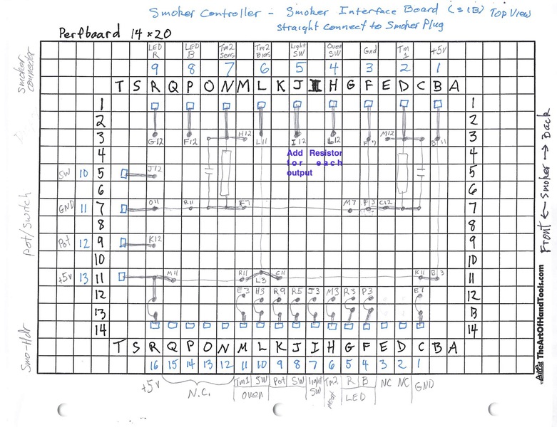
Smoker Interface Board (SIB)
The Nano Interface Board (NIB) has an Ardiuino Nano module soldered to the center of the board. A 16-pin header at the bottom connects to the SIB above. At the top of the graph, 8 wires are soldered to the board leading to an 8-wire Dupont connector and the DIB.
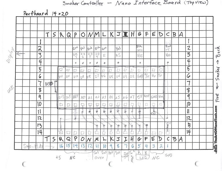
Nano Interfsce Board (NIB)
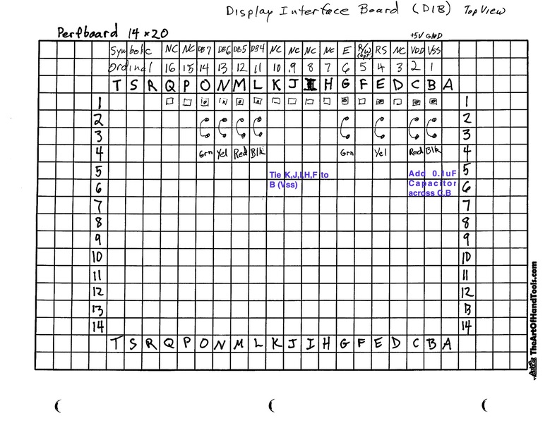
The Display Interface Board (DIB) has at the top a 16-pin header which mates to the OLED module. Soldered to these pins are 8 wires leading to an 8 pin Dupont connector for connection to the NIB. In this graph the pins 7-10 are shown as not connected (NC). These are the low order 4-bits not used when the display is in 4-bit mode. After reading that the module actually starts in 8 bit mode until the software sets 4-bit mode, I decided to tie these pins to GND (VSS). Also I added a 0.1uf capacitor between VDD and VSS to counter effects of the longer wires that this distributed design entails.
 9d. Board Assembly
D. Board Assembly
It is not feasible for me to create a circuit board that duplicates the OEM board and fits into the little box of the OEM control panel housing. However retaining the shape of the OEM front console is a requirement. Otherwise I would have to recreate the smoker’s top piece.
The control panel housing (aka console) is mounted at the top front of the smoking box ocupying a space above the door. This housing hangs off the front of the smoker box. The controller panel is mounted in a curved part of the console housing at a slight angle. The console surface is curved heavily at the ends and slightly in the middle. The effect of this is, I believe, to drain off rainwater as well as for visibility of the panel. But the internal shape of the housing makes installation of a replacement a real pain.
Here is the original control module:
In order to fit a custom device into the front panel of the MB 20070512, the replacement controller will be assembled from several pieces.
- plexiglass sheet, 1/8 inch thick, matching the dimensions of the OEM control screen
- OLED 16×2 display module attached to the backside of the plexiglass sheet. Because the 1/8 inch sheet is too thin to support screws, additional plexiglass strips are glued to the back of the sheet and these are drilled to accept standoff screws from the display module. The screws do not penetrate through the main plexiglass sheet.
- Display Interface Board (DIB) is attached via standoffs and a 16-pin header to the back of the OLED module
- Nano Interface Board (NIB) containing the Arduino Nano Every. The board is attached via standoffs to the right side,facing the front of the smoker, of the interior of the console piece.
- Smoker Interface Board (SIB) routing to the smoker is attached via standoffs to the top of the NIB
- one hole drilled into the front right side of the control panel for through-mounting a 5-pin potentiometer.
- two holes are drilled into the front right side of the control panel for status LEDs
After it’s all put together it looks like this:
I needed to thinks this through with drawings. Starting with a coding stick and graph paper, I migrated to using the Gliffy Chrome plugin.
This diagram shows the side view of the OLED module to plexiglass sheet assembly:
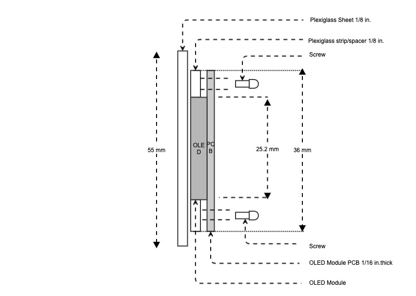
OLED Mounting to Plexiglass
The OLED to MCU integration is accomplished with an 8-wire bundle to allow the MCU board to be located somewhere else within the smoker’s front panel (which has ample space within it’s sides). At first, I chose to mount the MCU board directly behind the OLED module using standoffs and 16 pin headers but there was not enough room for a piggy-back design.
This diagram shows how the MCU board could have been attached to the back of the OLED display board:
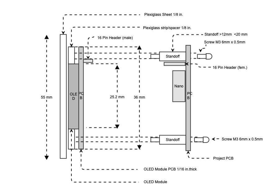
Notional Packaging
Not shown is the 5-pin potentiometer which is mounted to the console housing on the right side the smoker via a hole drilled into the housing. Also not shown are the screw terminal connector to the smoker system connector and the conditioning circuits for the thermistors and status LEDs.
The thickness of the assembled package is between 3/4 to 1 inch depending on the standoffs used. This exceeds the clearance between the angled portion of the console housing and the smoker body. So I have to abandon the notion of stacking all the circuitry on top of the OLED module.
Off to either side of the console housing there is plenty of room for two stacked boards.
Below is a notional, non-scale drawing of the mounting as viewed from the back of the display. The actual pieces cut are longer to provide more area to drill holes into. Plexigrass is very fragile so the pieces need to be larger than shown here.
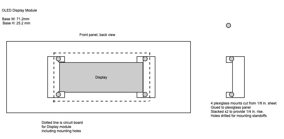
OLED Mounting – Back View
Below is the cut plexiglass sheet with the mounting braces glued on. I cut this using a coping saw and sanded the ends smooth. Very tedious! A laser cutter/engraver would have made short work of this, but for the cost. The protective wrapper is still on the outer face to keep me from scratching the face. Gluing plexiglass is an art. One that I am not so good at. The pieces will slide into the wrong position if not held in place. Pressure needs to be applied to remove air from between the pieces. I discovered that even tiny gaps between the surfaces will compromise the transparency of the whole. If properly done the joining would be invisible. In my case I was left with internal reflections and obvious signs of gluing.
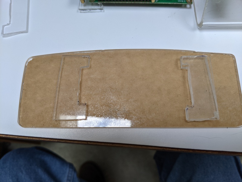
Plexiglass Panel With Braces
After filing and sanding, the panel fits pretty good. But the gluing is a bit messy.
Plexiglass Fitting into Console
Now my plan is to spray paint the back side of the plexiglass, masking off the display port, to give a nice shiny appearance. When I did that the artifacts of the gluing showed even more prominently:
Panel Backside Painted
So I will now paint the front of the panel. I could have just bought black plexiglass!
The following picture, created using Fritzing, shows logical connections between the components. Ideally the three modules would have been stacked, but for the spacial constraints. The picture shows 16-pin headers connecting the layers. The alternative, forced by lack of space, distributes the boards within the smoker’s console housing piece and connects them via lengths of wire. Two pieces of 4-conductor phone wire were used since I have plenty of it. CAT-5 8-wire would have been better, as it is more flexible, but my color perception makes that a challenge.
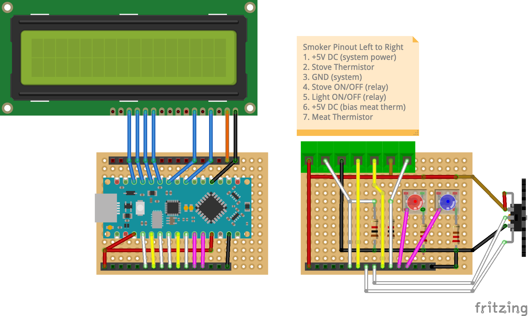
Smoker Controller Prototype in Fritzing
The finished DIB:
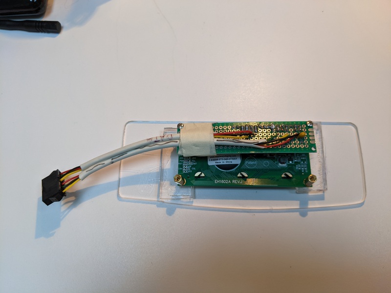
Display Interface Board
The finished NIB:
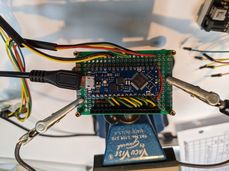
Nano Interface Board
The NIB back:
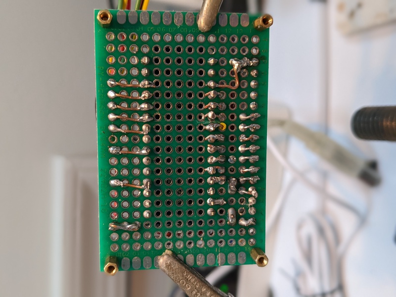
NIB Backside
The SIB top side:

Smoker Interface Board
The SIB back:
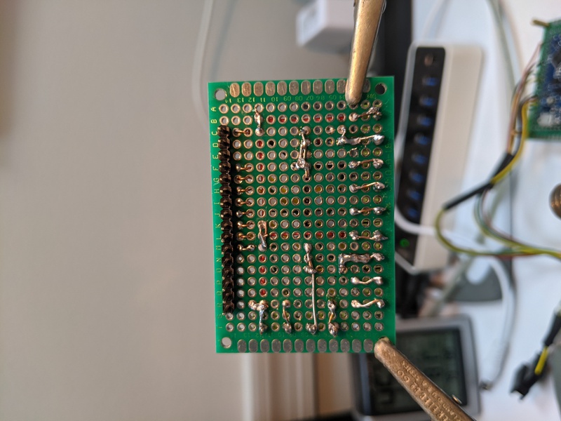
SIB Backside
Assembling the NIB and the SIB gives me a compact module. I would like to enclose this in a water resistant enclosure but not for this go around.
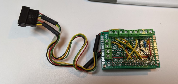
NIB SIB Assembled Module
The bottom of the stand-offs has just enough thread to protrude from the bottom of the console. I drilled four holes in the console using a blank perfboard as a template, taped in place. The console is warped so I can’t get nuts to thread on all four stand-offs but I think it will hold.
A power on test run does not make smoke, so that is good. Smoke at this stage of the project would not be good
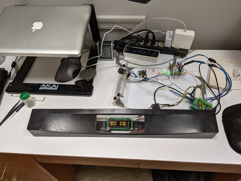
Test Run
An assembly test run shows it all fits. However there is a lot of wire and it is pretty stiff. I resolve to re-do the wiring using CAT-5 or similar stranded wire. But I really do not relish the thought of making new Dupont connectors. My crimper and the parts to be crimped seem to disagree on some basic dimensions.
The Assembly
The LED indicators were created using plastic glass stops for a glass patio table. I bought a bag of these and was looking for other uses. It turns out that the plexiglass, the smoker console, and the plastic stops all bind together using the same solvent glue. I thought at first to attach the indicators to the back of the plexiglass so that they would shine through. I finally decided to drill two 1/4 inch holes in the console for through mounting. So I insert the plastic stop into a section of shrink tubing. Solder a resistor onto an LED and insert the LED into the other end of the shrink tubing. Heat it up and I have a light pipe.
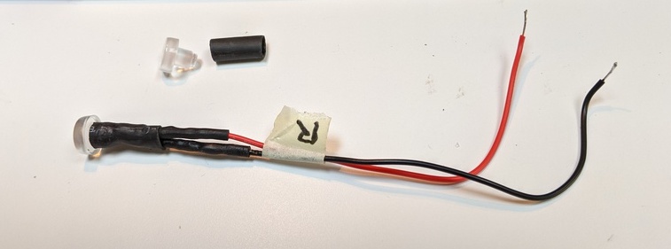
LED Light Pipe
The assembly slides snugly into the 1/4 inch hole and a little glue holds it in. Hopefully the glue seals against moisture.
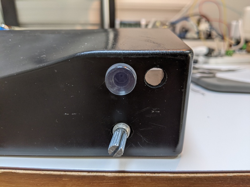
LED Mounted
After it’s all put together it looks like this:
9e. Display Wiring
E. Display Module Wiring
Display Module
Display modules are available in a common format pattern after the Hitachi LCD Module.
I chose an OLED module for its display characteristics. It shows bright monochrome characters against a true black backgound with no backlighting.
The New Haven Display model NHD-0216-KZW-AG5 is pin compatible and software compatible with the common LCD format. Available from Digi-Key, and others, in green, blue, and yellow.
Each module supports three wiring options: 8-bit parallel, 4-bit parallel, and serial. The default option is 4-bit parallel which is perfect for my application. I only need to use 4 data pins, 9 pins in all.
In 4-bit mode each 8-bit byte is sent separately as two 4-bit nibbles.
            DB7  Nibble bit 3 (high order)
DB6  Nibble bot 2
DB5  Nibble bit 1
DB4  Nibble bit 0 (low order)
E    Enable (data strobe)
R/W  Read/Write select 0=write 1=read (optional)
RS   Register select 0=command 1=data
VDD  +5V
VSS  Ground
The wiring option is mostly transparent to an Arduino application using the LiquidCrystal library. Data is put to the display as strings via set-cursor and print methods of the library. The library provides different constructors for specifying the pin configuration. Note that the R/W pin is optional as writing is the default and read is not needed for this application.
Arduino
I’ll be using an Arduino Nano Every for the Smoker Controller, although I also use a Mega 2650 for prototyping and discovery.
The display module is connected to the Every as follows:
            Nano        OLED Module (4-bit)
---------   -------------------
            (16) Not used (no backlight w/OLED)
            (15) Not used (no backlight w/OLED)
(12) D10    (14) DB7
(11) D9     (13) DB6
(10) D8     (12) DB5
(9)  D7     (11) DB4
            (10) DB3 (not used w/4-bit)
            (9)  DB2 (not used w/4-bit)
            (8)  DB1 (not used w/4-bit)
            (7)  DB0 (not used w/4-bit)
(8)  D6     (6)  E
     D5     (5)  R/W (not used w/only writing)
(7)  D4     (4)  RS
            (3)  Not used (no contrast adj. w/OLED)
(27) +5V    (2)  VDD
(29) GND    (1)  VSS
Note that the R/W pin should be tied to GND if no READ is to be used.
Note that some sources suggest that the 4 low bits not used in 4-bit mode should be tied to GND to prevent glitches during initalization, when the module is still in its initial 8-bit mode.
The Arduino LiquidCrystal library contructor for this configuration is:
            //    OLED symbol RS E  D4 D5  D6  D7
//    OLED pin #  4  6  11 12  13  14
//    NANO pin #  7  8  9  10  11  12
LiquidCrystal lcd(7, 8, 9, 10, 11, 12);